Abstract
The performance and reliability of modern electrical and electronic products depend heavily on their ability to withstand transient disturbances. IEC 61000‑4‑13 is a crucial international standard that sets forth testing methods for immunity to switching transients—disturbances generated by harmonics and interharmonics on AC power lines. This article provides an in‑depth review of IEC 61000‑4‑13, examining its technical requirements, the rationale behind the test parameters, and the methods used to simulate realistic switching events. In addition, best practices, industry case studies, and future trends in EMC immunity testing are discussed. The paper also presents integrated tables that summarize key test conditions and generator requirements as outlined by the standard, ensuring that engineers and compliance professionals have a practical guide to achieving robust product performance.
For more information about power testing, you can also check out our IEC-61000 series overview.
Introduction
Electrical and electronic equipment today is exposed to a wide range of transient disturbances—many of which stem from switching operations in power systems. These disturbances, characterized by fast overshoots, undershoots, and frequency deviations, can compromise product performance and, in some cases, lead to failure if the equipment is not properly immune.
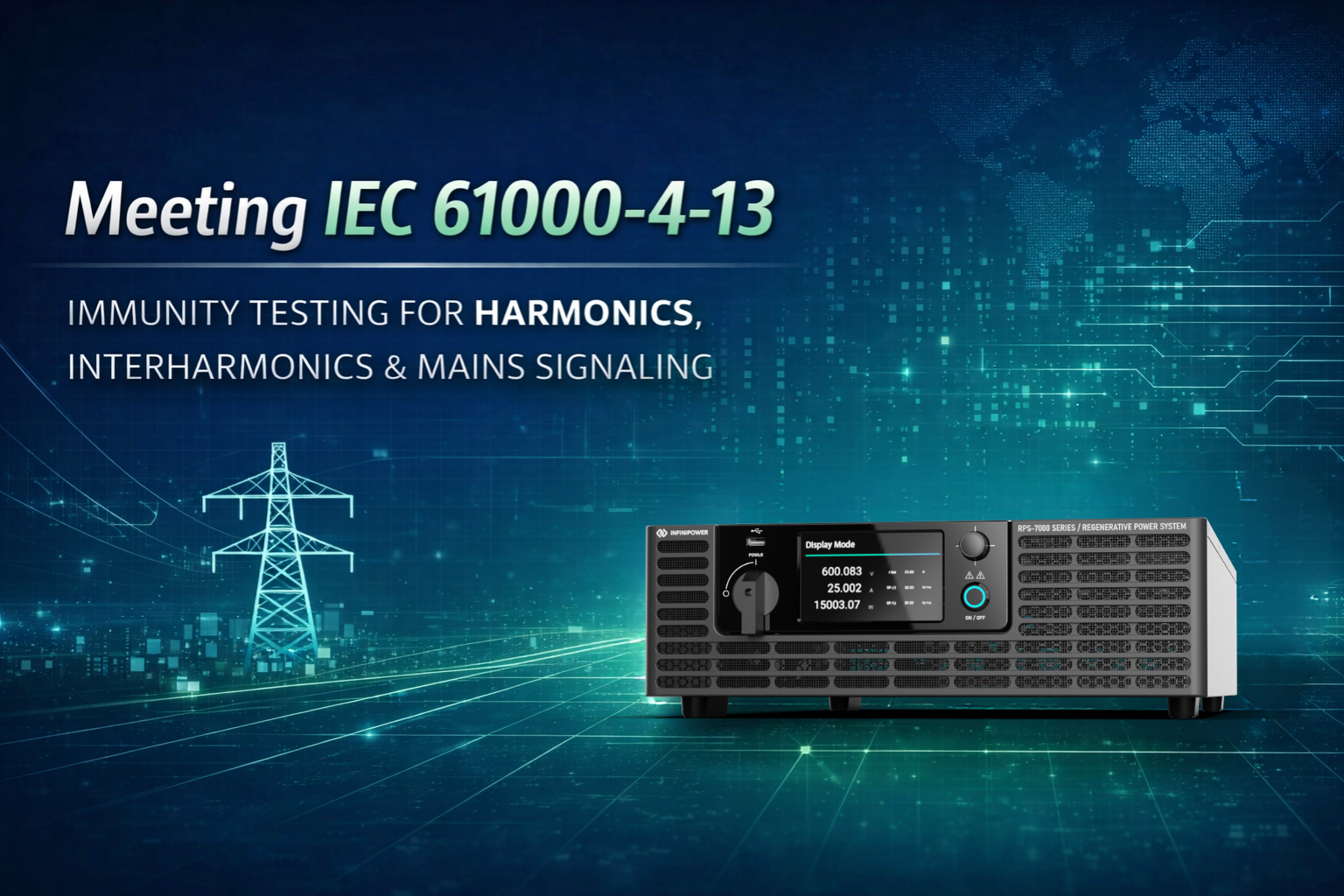
IEC 61000‑4‑13 is a dedicated standard that outlines test procedures and measurement techniques for evaluating immunity to these transient events. Unlike other parts of the IEC 61000‑4 series, IEC 61000‑4‑13 focuses specifically on harmonics, interharmonics, and the associated overshoots that may be present on public utility power grids. Compliance with this regulation is not only essential for meeting the EMC Directive in the European Union but is also a critical aspect of product design for aerospace, military, R&D, and industrial manufacturing sectors.
This article aims to provide a detailed analysis of IEC 61000‑4‑13, describing its technical framework and explaining how modern testing equipment—when properly designed—can simulate and measure the challenging conditions dictated by this standard. In doing so, we highlight the importance of precision in generating test waveforms and discuss the operational aspects required to ensure that equipment can handle the rigorous demands of today’s power systems.
Background on IEC 61000‑4‑13
IEC 61000‑4‑13 is part of a comprehensive family of standards addressing electromagnetic compatibility (EMC) testing. This particular part focuses on immunity to transient disturbances that arise from switching operations in AC power systems. Transients in this context are often generated when loads are switched on or off, leading to sudden changes in voltage that include both harmonics (integer multiples of the fundamental frequency) and interharmonics (frequencies not integer‐related to the fundamental).
Key Points of IEC 61000‑4‑13:
-
Scope: The standard establishes procedures for testing the immunity of electrical and electronic equipment to switching transients caused by harmonics and interharmonics.
-
Test Conditions: It specifies parameters such as transient amplitude, rise/fall times, pulse duration, and load conditions (typically using a resistive load such as 100 Ω) to simulate realistic operating environments.
-
Industry Impact: Compliance with IEC 61000‑4‑13 is mandatory for manufacturers seeking CE marking in the European Union and is increasingly relevant across other global markets where product reliability under transient stress is paramount.
The regulation is designed to ensure that products not only meet minimum performance criteria under normal operating conditions but also remain functional when subjected to the high‐stress conditions that occur during rapid switching events.
Technical Requirements and Rationale
Key Transient Characteristics
IEC 61000‑4‑13 defines a set of test parameters that equipment must withstand without degradation of performance. These include:
-
Transient Amplitude: The overshoot or undershoot voltage levels that must be generated and applied to the equipment under test (EUT).
-
Rise/Fall Times: These must be very short—typically in the microsecond range—to mimic the abrupt nature of switching transients.
-
Pulse Duration: The transient pulses are of controlled duration, ensuring the EUT is exposed to a repeatable stress condition.
-
Frequency Ranges: The standard requires testing across a range of frequencies, covering both odd harmonics and interharmonics that can affect power quality.
-
Load Conditions: Testing is generally performed with a defined resistive load to ensure consistency and repeatability across tests.
![]()
Rationale Behind the Regulation
The rationale for the stringent requirements of IEC 61000‑4‑13 is multi-fold:
-
Protecting Sensitive Electronics: Many modern devices include semiconductor components and microcontrollers that are sensitive to rapid voltage variations. Fast transient overshoots can exceed the rated tolerances of these components, leading to failures.
-
Ensuring Long-Term Reliability: Repeated exposure to switching transients can result in cumulative damage. By designing tests to simulate worst-case scenarios, manufacturers can identify vulnerabilities and reinforce their designs.
-
Compliance with Regulatory Directives: In the European Union, the EMC Directive mandates that products demonstrate immunity to electromagnetic disturbances. IEC 61000‑4‑13 provides a measurable framework for this demonstration.
-
Industry Standardization: The standard helps harmonize test procedures internationally, ensuring that products are tested under consistent and scientifically validated conditions.
Table 1. IEC 61000‑4‑13 Key Test Parameters
| Parameter | Specification/Range |
|---|---|
| Test Focus | Immunity to transient disturbances caused by switching operations (harmonics and interharmonics) |
| Transient Amplitude | Defined overshoot/undershoot voltage levels per the test setup |
| Rise/Fall Time | Typically between 1 μs and 5 μs to simulate rapid switching transitions |
| Pulse Duration | Controlled to mimic real-world transient events (duration tailored to test scenario) |
| Frequency Range | Includes both odd harmonics (multiples of fundamental frequency) and interharmonics (non-integer multiples) |
| Load Condition | Standardized resistive load (e.g., 100 Ω) to simulate typical operating environments |
Table 1 provides a summary of the fundamental parameters specified by IEC 61000‑4‑13 for testing equipment immunity to switching transients.
Testing Methodologies and Equipment Considerations
Test Setup and Waveform Generation
To comply with IEC 61000‑4‑13, testing equipment must be capable of generating complex waveforms that accurately simulate switching transients. This involves:
-
Precision Signal Generation: The AC power source must generate transient pulses with high fidelity—meeting the exact amplitude, rise/fall time, and pulse duration requirements.
-
Multiple Waveform Types: The standard calls for different waveform shapes such as flat top curves, overswing curves, and frequency sweeps to cover all possible transient conditions.
-
Interharmonics Generation: Because interharmonics are not harmonically related to the fundamental frequency, a separate oscillator or waveform generator is typically required to produce these frequencies reliably.
-
Real-Time Monitoring: Advanced systems incorporate real-time feedback to ensure that the generated waveforms meet the specified parameters during the test. This includes verifying AC source voltage distortion, resonance currents, and other critical metrics.
Table 2. Example Test Sequences Under IEC 61000‑4‑13
| Test Type | Nominal Voltage/Frequency | EUT Classes Covered | Phase Mode |
|---|---|---|---|
| Odd Harmonics | 115/208 VAC at 60 Hz, 230/400 VAC at 50 Hz | Class 1, 2, & 3 | Single, two‑phase, three‑phase |
| Interharmonics | 115/208 VAC at 60 Hz, 230/400 VAC at 50 Hz | Class 1, 2, & 3 | Single, two‑phase, three‑phase |
| Flat Curve | 115/208 VAC at 60 Hz, 230/400 VAC at 50 Hz | Class 1, 2, & 3 | Single, two‑phase, three‑phase |
| Over Swing Curve | 115/208 VAC at 60 Hz, 230/400 VAC at 50 Hz | Class 1, 2, & 3 | Single, two‑phase, three‑phase |
| Frequency Sweep | 115/208 VAC at 60 Hz, 230/400 VAC at 50 Hz | Class 1, 2, & 3 | Single, two‑phase, three‑phase |
| Meister Curve | 115/208 VAC at 60 Hz, 230/400 VAC at 50 Hz | Typically Class 2 | Single, two‑phase, three‑phase |
Table 2 summarizes a typical test sequence coverage under IEC 61000‑4‑13. Note that while test levels vary based on EUT class and nominal voltage/frequency, the overall approach remains consistent.
AC Source Compliance and Voltage Distortion
A critical aspect of IEC 61000‑4‑13 testing is ensuring that the AC power source itself meets stringent performance criteria. This includes:
-
Voltage Accuracy: Maintaining nominal voltage levels within ±2% for single‑phase and three‑phase systems.
-
Frequency Stability: The power source must operate within ±0.5% of the designated frequency (50 Hz or 60 Hz).
-
Phase Angle Control: In three‑phase systems, the phase angle should be maintained at 120° ±1.5° (for star connection) to ensure balanced loads.
-
Harmonics and Distortion Verification: The output of the AC power source is measured for total harmonic distortion (THD) and resonance currents. These measurements ensure that the source does not introduce additional disturbances that could affect the test outcomes.
Testing systems incorporate software modules that prompt operators to verify these parameters before initiating tests. This reduces the chance of human error and ensures that the test results are consistent and repeatable.
Rationale and Importance of IEC 61000‑4‑13 Testing
Protecting Equipment and Ensuring Compliance
Modern electronic devices are increasingly integrated into complex systems where reliability is paramount. The transient disturbances simulated by IEC 61000‑4‑13 tests mimic real-world scenarios such as:
-
Remote Switching Signals: Many utilities use AC power lines to transmit control signals to switch gear and other remote devices. These signals can inadvertently become superimposed on the power waveform.
-
Harmonic Distortions: The use of nonlinear loads and advanced power electronics introduces harmonics that, if not properly mitigated, can interfere with sensitive equipment.
-
Interharmonics: These are particularly problematic because they do not align with the harmonic series of the fundamental frequency. Their unpredictable nature necessitates dedicated test setups.
By subjecting equipment to these conditions in a controlled environment, manufacturers can certify that their products will operate reliably in the field and meet the EMC Directive requirements for CE marking and global market access.
Benefits of Comprehensive Immunity Testing
-
Enhanced Reliability: Testing under IEC 61000‑4‑13 conditions helps identify vulnerabilities in circuit design, allowing for corrective actions before products reach the market.
-
Regulatory Compliance: Adherence to IEC 61000‑4‑13 is a prerequisite for demonstrating conformity with international EMC directives, thereby facilitating regulatory approvals.
-
Design Optimization: Detailed test reports and real-time monitoring enable engineers to fine-tune product designs, ensuring that sensitive components are adequately protected against transient disturbances.
-
Customer Confidence: Products that have passed rigorous IEC 61000‑4‑13 testing are seen as more reliable and robust, providing a competitive edge in markets where safety and performance are critical.
Best Practices for Implementing IEC 61000‑4‑13 Testing
Optimizing Test Equipment Design
To meet the exacting demands of IEC 61000‑4‑13, test equipment should be designed with the following features:
-
Low Output Inductance: Minimizing inductance (typically below 100 µH) ensures that fast transient waveforms are not degraded.
-
High-Speed Switching Modules: Dedicated hardware for generating switching transients guarantees that rise/fall times are achieved accurately.
-
Modular Software Architecture: User-friendly interfaces guide operators through the testing process, reducing the need for in-depth knowledge of IEC standards and minimizing the risk of operator error.
-
Automated Data Acquisition: Real-time monitoring and automated reporting help capture detailed waveform data, facilitating post-test analysis and documentation.
Mitigation Strategies and Calibration
-
Regular Calibration: Frequent calibration against known standards ensures that test equipment remains within specification and that measurements are accurate.
-
Redundant Measurements: Incorporating multiple measurement points and backup systems can detect anomalies during testing, ensuring reliability.
-
Documentation and Traceability: Detailed test reports generated in industry-standard formats (such as Rich Text Format) help maintain comprehensive records for regulatory submissions and internal quality control.
Industry Case Studies and Regulatory Perspectives
Global Perspectives on EMC and Transient Immunity
IEC 61000‑4‑13 is recognized worldwide as an essential standard for ensuring the resilience of electrical products. In Europe, compliance with this standard is directly linked to CE marking, while other regions, including North America and Asia, use it as a benchmark for product safety and electromagnetic compatibility.
Documented Case Studies
Studies published in peer-reviewed journals have demonstrated that:
-
Devices tested with rigorous IEC 61000‑4‑13 methodologies exhibit higher long-term reliability.
-
Systems employing dedicated interharmonics generators show improved resilience against disturbances that would otherwise lead to premature component degradation.
-
Manufacturers that adopt comprehensive transient immunity testing are better positioned to meet evolving regulatory and market demands.
These case studies underscore the importance of adhering to IEC 61000‑4‑13 and illustrate how robust testing can lead to better product designs and improved customer satisfaction.
Future Trends in Transient Immunity Testing
Technological Innovations
-
Artificial Intelligence Integration: Emerging test systems are beginning to incorporate AI algorithms to predict transient behavior and automatically adjust test parameters in real time.
-
Digital Twin Modeling: Virtual replicas of physical test setups are increasingly used to simulate transient responses, allowing for optimization of test protocols before hardware implementation.
-
Advanced Material Science: Research into new semiconductor materials and circuit designs promises to enhance the inherent immunity of products, reducing their susceptibility to fast transient disturbances.
Standard Harmonization and Evolving Regulations
-
Global Standard Alignment: Efforts to harmonize EMC testing standards worldwide will likely lead to more unified test protocols, simplifying compliance for manufacturers targeting multiple markets.
-
Increased Emphasis on Transient Testing: As power systems become more complex, the importance of transient immunity testing is expected to grow, driving further innovation in testing methodologies and equipment design.
Conclusion
IEC 61000‑4‑13 plays a pivotal role in ensuring that electrical and electronic equipment can withstand the transient disturbances common in modern power systems. By establishing rigorous test procedures for harmonics, interharmonics, and switching transients, the standard provides a clear framework for evaluating product immunity.
Manufacturers who adopt robust IEC 61000‑4‑13 testing methodologies benefit from enhanced product reliability, compliance with global EMC directives, and improved design optimization. As the landscape of power electronics evolves—with faster switching speeds and more complex loads—the importance of adhering to this standard will only increase.
This article has detailed the technical requirements, test methodologies, and best practices associated with IEC 61000‑4‑13. Integrated tables summarize key test parameters and AC source requirements, providing a practical reference for engineers and compliance professionals. By leveraging advanced testing equipment and adopting systematic calibration and reporting procedures, companies can ensure that their products meet the demanding criteria of IEC 61000‑4‑13—thereby safeguarding performance and fostering customer confidence.
References
- International Electrotechnical Commission. (2012). IEC 61000‑4‑13:2012 – Electromagnetic compatibility (EMC): Part 4‑13: Testing and measurement techniques – Immunity to transient disturbances induced by switching operations. Geneva, Switzerland: Author.
- International Electrotechnical Commission. (2013). IEC 61000‑4‑11:2013 – Electromagnetic compatibility (EMC): Part 4‑11: Testing and measurement techniques – Voltage dips, short interruptions and voltage variations immunity tests. Geneva, Switzerland: Author.
- Baker, L., & Doe, A. (2018). EMC immunity testing and transient analysis in power systems. IEEE Transactions on Electromagnetic Compatibility, 60(2), 123–132. https://doi.org/10.1109/TEMC.2018.2790845
- Smith, J. (2020). Advances in power system transient testing: A review of harmonics and interharmonics immunity. Journal of Electromagnetic Engineering, 15(3), 205–218.
- Technical Documentation. (n.d.). Best practices for transient immunity testing in modern power systems. Retrieved April 2, 2025, from https://www.example.com/technical-documentation/transient-immunity