800 kW Integrated System
Scalable to 8 MW
800 kW Integrated System
Scalable to 8 MW
INTEGRATED POWER TESTING
Regenerative AC/DC Source, Load & Grid Simulator
Validate high-power systems under real-world conditions.
Bring AC/DC sourcing, regenerative loading, and grid simulation into one configurable test platform. The RPS-9000 supports development and validation of AI power infrastructure, megawatt charging systems, energy storage, and grid-connected converters.
Reproduce voltage dips, frequency variations, phase shifts, and harmonic disturbances to evaluate system response and protection behavior. High-current output and synchronized parallel operation support demanding test loads, while up to 90% energy recovery helps reduce facility power demand during regenerative testing.
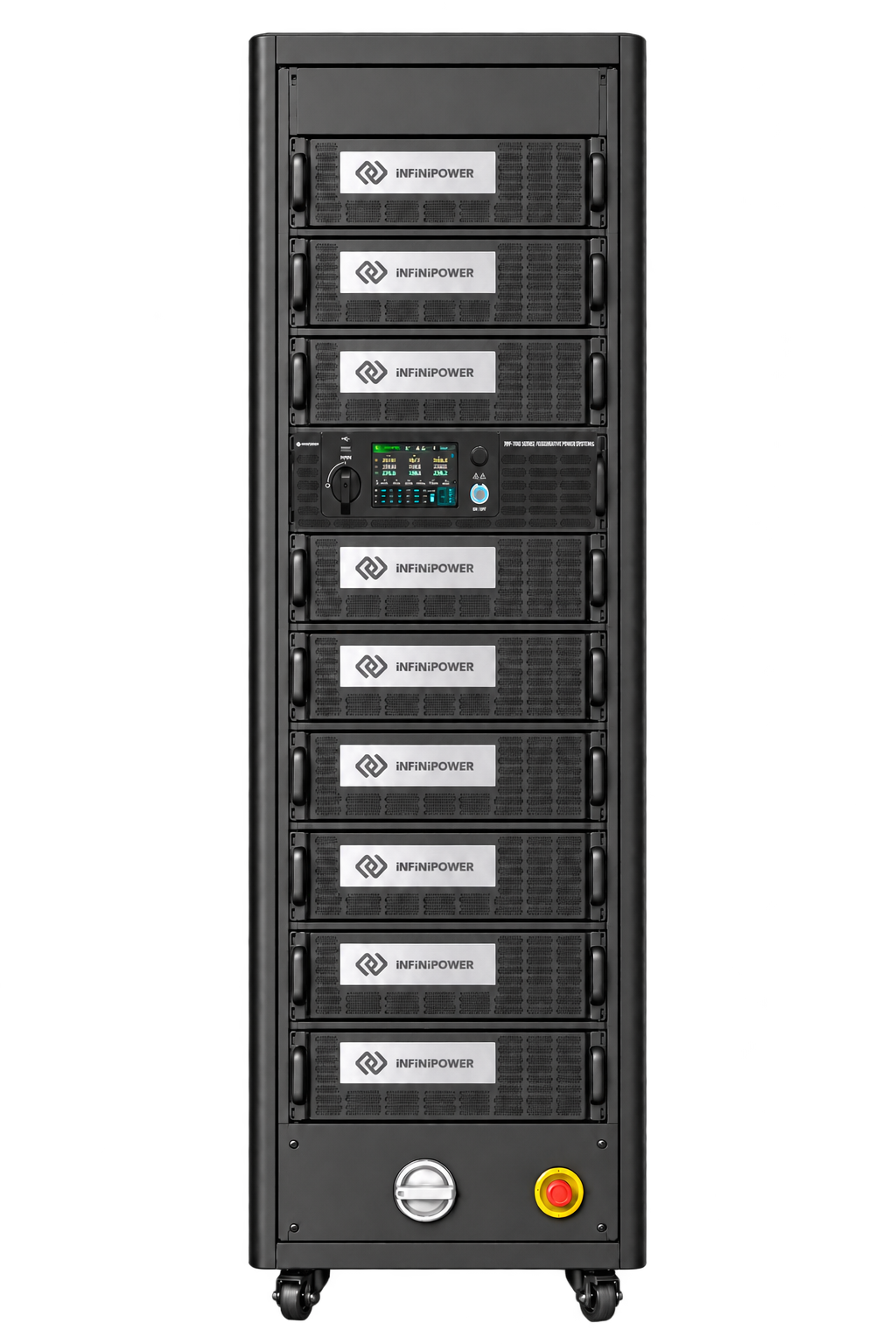
Main specifications and applications
KEY FEATURES
- 202.5–810 kVA / kW model ratings
- Parallel system expansion up to 8 MW
- Four-quadrant regenerative AC/DC operation
- Integrated source, load and grid simulation; configuration dependent
- Up to 90% regenerative energy recovery
- Up to 5,184 Arms single-phase output (RPS-9800, at 125 V)
- Single-phase, three-phase and split-phase output
- 0–350 V L-N AC output; 400 V optional
- DC, 30–150 Hz; 30–1000 Hz optional
- CV, CC and CP source operation
- LIST, STEP, PULSE and TRANSIENT modes
- Standard, distorted and user-defined waveforms
- Harmonic synthesis through the 50th order at 50/60 Hz
- USB, Ethernet, GPIB and external I/O; CAN Bus optional
APPLICATIONS
- AI data centers and high-density GPU infrastructure
- Megawatt Charging Systems and DC fast chargers
- Commercial EVs and heavy-duty electric vehicles
- Battery Energy Storage Systems and PCS
- Grid-Forming and Grid-Following inverters
- Solar PV and wind power conversion
- Utility grid simulation and compliance validation
- HVDC and industrial power electronics
- Power Hardware-in-the-Loop and system-level validation
Built for Real-World Power Validation
High-Current Output
Model-specific single-phase output from 1,296 to 5,184 Arms supports demanding power electronics testing. Maximum RMS current is specified at 125 V.
Scalable Capacity
Expand from 202.5 kVA / kW to integrated configurations up to 810 kVA / kW, with parallel systems up to 8 MW.
Regenerative Operation
Recover up to 90% of energy during regenerative operation to reduce facility power demand.
Integrated Test Capability
Source, regenerative load, waveform generation, and grid simulation support development and system validation.
System-Level Validation
Support AI infrastructure, megawatt charging, energy storage, and renewable power conversion.
AIoT Predictive Maintenance
Real-time monitoring and intelligent diagnostics minimize downtime and improve operational reliability.
RPS-9000 ENGINEERING ADVANTAGES
True High-Current Capability
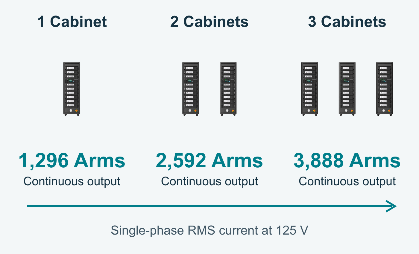
The RPS-9000 delivers high current at low voltages for AI servers, megawatt charging, and battery platforms.
One to three cabinets provide 1,296–3,888 Arms of continuous single-phase output at 125 V. The referenced three-cabinet configuration supports peaks up to 11,664 Apk, subject to operating conditions.
Up to 90% energy recovery helps reduce facility power demand.
High-Speed Synchronization Minimizes Circulating Current
Conventional parallel systems can introduce communication latency and synchronization mismatch, leading to circulating current, thermal stress, power derating, and waveform distortion.
The RPS-9000 combines high-speed DSP control and FPGA-based hardware synchronization to minimize circulating current and enable stable, scalable high-power operation.
Reducing Voltage Overshoot
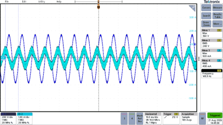
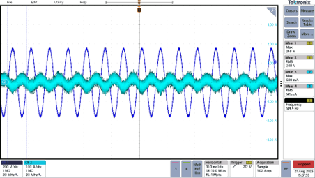
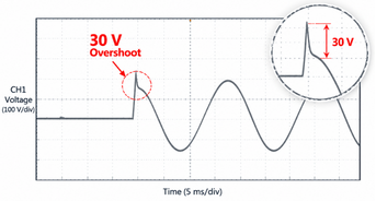
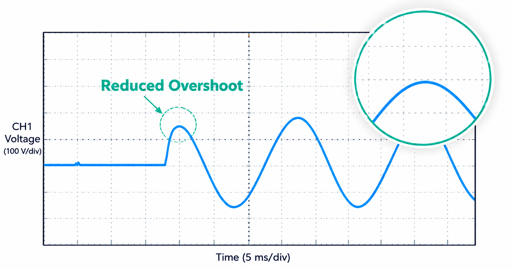
Traditional external parallel architectures can experience voltage overshoot during fast dynamic transitions.
The RPS-9000’s high-speed internal synchronization architecture improves transient response and reduces voltage overshoot, helping ensure stable output and reliable DUT protection.
Coordinated Control as Test Capacity Expands
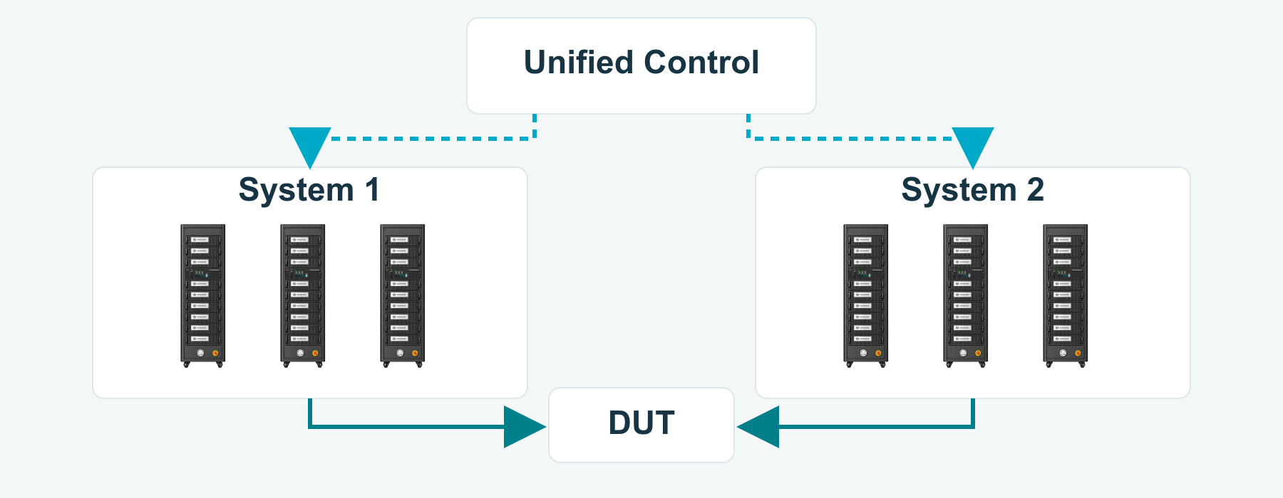
Increasing test capacity should not require engineers to operate each system separately. The RPS-9000 supports coordinated parallel operation through a unified control interface.
Engineers can manage an expanded test configuration as one platform, simplifying output setup and operation as power requirements grow.
Energy Recirculation for High-Power Testing
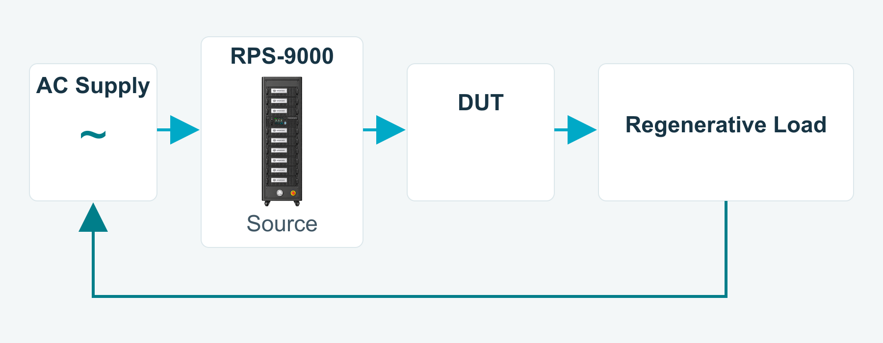
High-power validation requires careful planning of facility power demand. In a test system equipped with a regenerative electronic load, energy from the DUT can be returned to the AC supply for reuse.
The RPS-9000 can form the source side of this test architecture, supporting extended testing of power converters and AI power infrastructure. Overall facility demand depends on the DUT, operating point, and efficiency of each system component.
Everything You Need for Power Validation
Beyond Standard Waveforms
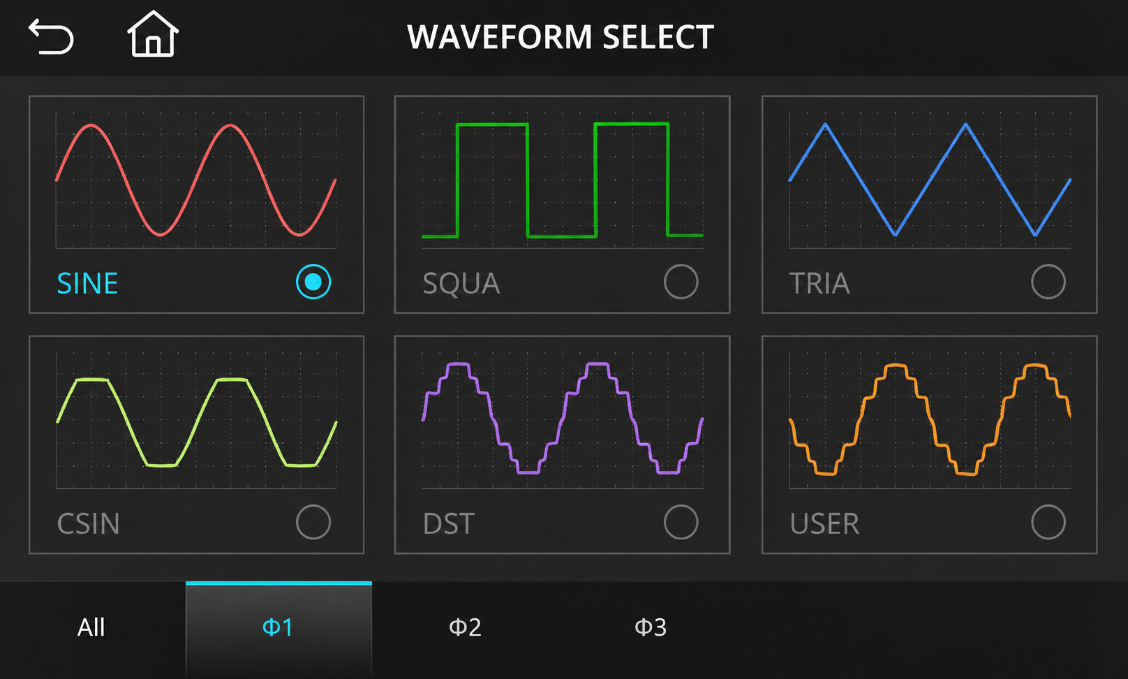
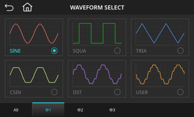
The RPS-9000 generates standard signals, distorted waveforms, and user-defined profiles to reproduce real-world grid characteristics. Built-in libraries help engineers configure repeatable power-quality tests for AI infrastructure, EV charging, energy storage, and renewable power conversion.
Supported Waveforms
- Sine Wave – Standard utility power simulation
- Square Wave – Fast switching and control system testing
- Triangle Wave – Dynamic response and analog circuit evaluation
- Clipped Sine Wave – Simulation of distorted utility waveforms
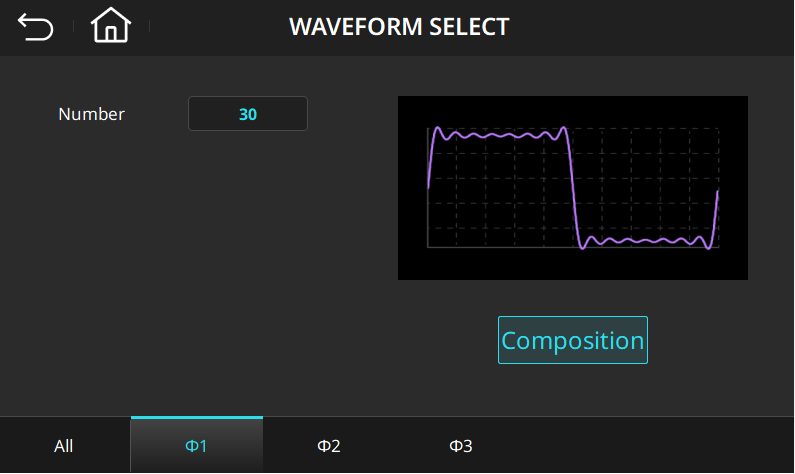
- Built-in Distortion Waveforms (DST) – 30 preconfigured distortion profiles for rapid power quality testing
- User-defined Waveforms – Create custom waveforms for application-specific validation
Comprehensive Simulation Capabilities
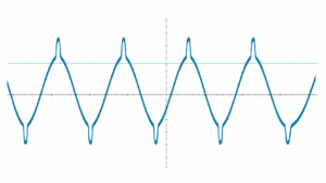
Program the amplitude and phase angle of individual harmonics from the 2nd through the 50th order at a 50/60 Hz fundamental. Interharmonic simulation adds non-integer-frequency components with adjustable frequency, amplitude, and duration to evaluate immunity and control stability.
Simulate voltage dips, frequency variations, phase jumps, LVRT, and HVRT for grid-connected equipment. Test functions support validation workflows associated with IEC 61000, IEEE 1547, UL 1741, and IEC 62116; available routines depend on the selected configuration.
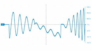
Voltage Dip (Step mode)
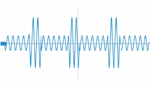
Surge (Pulse Mode)
Harmonic Distortion (Synthesis Mode)
Grid Disturbance & Transient Simulation
The RPS-9000 provides LIST, STEP, PULSE, and TRANSIENT modes to reproduce grid variations and abnormal events. Apply rapid voltage and frequency steps, programmable pulse profiles, and controlled sags or surges to evaluate DUT response and protection behavior.
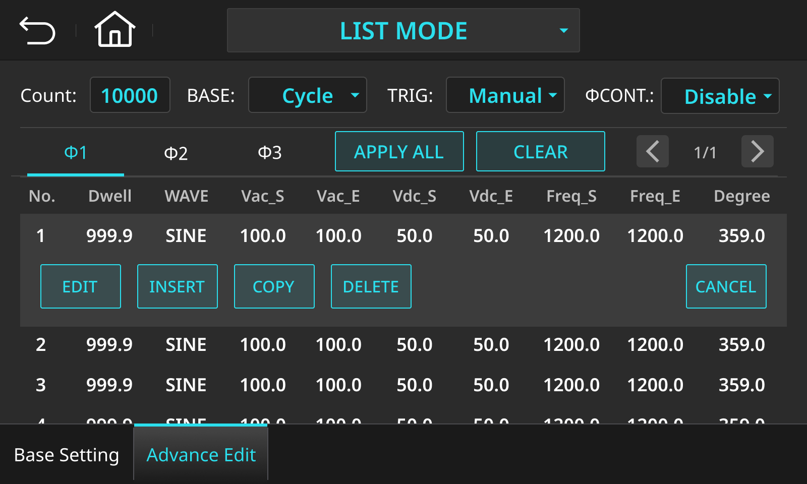
LIST Mode
Create multi-step programmable test sequences with configurable voltage, frequency, waveform, dwell time, and cycle count for long-duration testing, automated validation, and compliance verification.
PULSE Mode
Simulate short-duration voltage variations with adjustable amplitude, duty cycle, and pulse width to verify transient immunity and protection performance.
TRANSIENT Mode
Accurately reproduce voltage sag, surge, and other transient grid events with programmable phase angle, duration, amplitude, and positive or negative half-cycle characteristics.
Output Modes Overview
Choose the right output configuration to meet your test requirements
Single-Phase Mode
Combine output capacity into one phase for high-current supplies, EV chargers, and demanding single-phase equipment. A dedicated parallel output fixture supports high-current connections.
Three-Phase Mode
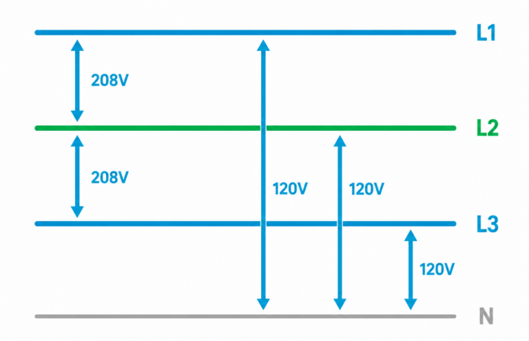
Set voltage, frequency, and phase angle per phase. Positive and negative phase sequences and independent controls support imbalance and grid-disturbance testing.
Split-Phase Mode
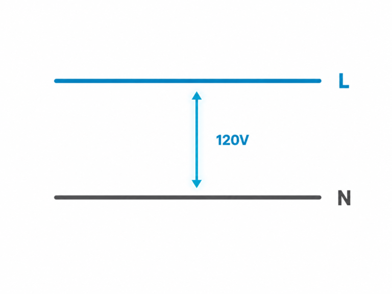
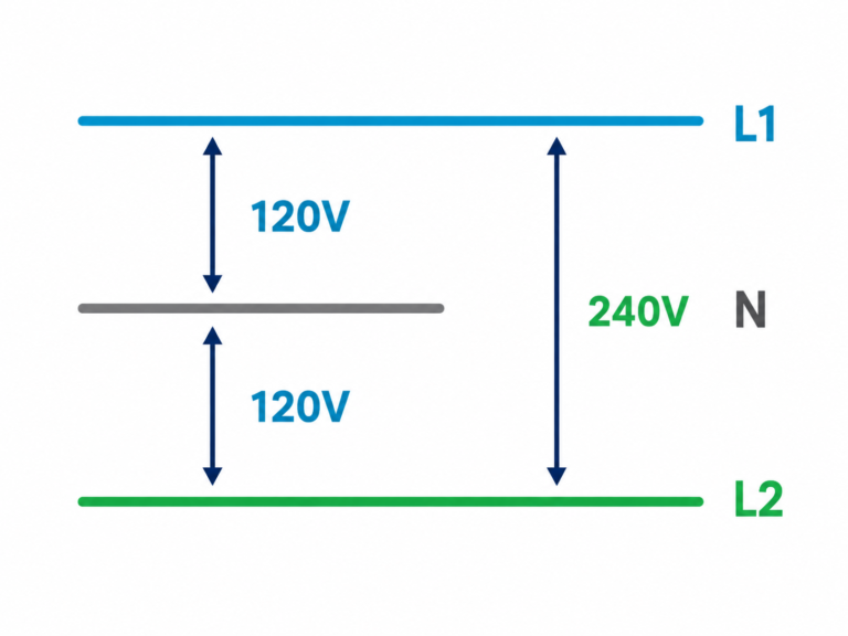
Simulate split-phase systems up to 700 V L-L, or 800 V L-L optional. Split-phase operation provides two-thirds of the selected model’s rated power.
Instant Access to Critical Electrical Measurements
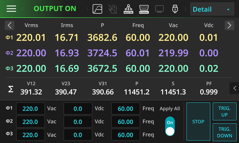
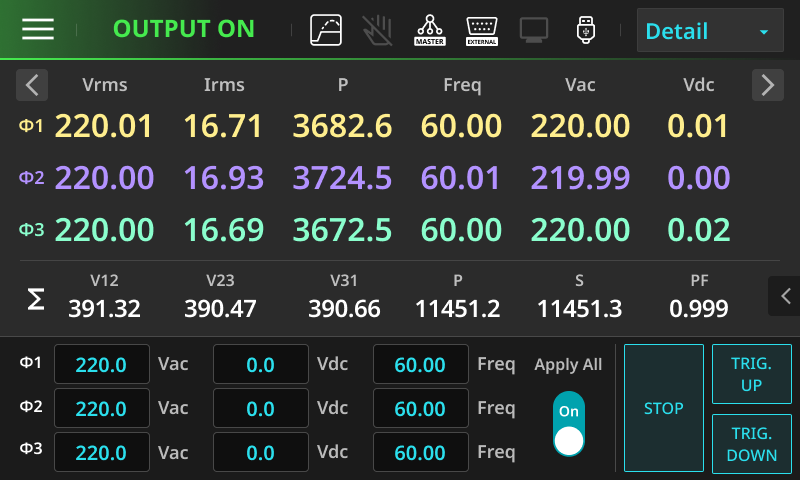
The RPS-9000 provides Simple and Detail measurement displays. Switch between essential operating data and comprehensive electrical analysis while output remains active.
Simple Mode presents three key electrical parameters in a large, easy-to-read layout, enabling operators to monitor critical measurements at a glance. It is ideal for equipment setup, production testing, routine operation, and long-distance monitoring.
Detail Mode displays up to 15 electrical parameters on a single screen, including voltage, current, power, frequency, power factor, crest factor, and additional AC/DC measurements. Engineers can simultaneously monitor comprehensive electrical characteristics for product validation, power quality analysis, and troubleshooting.
Gain Deeper Insight into Power Quality
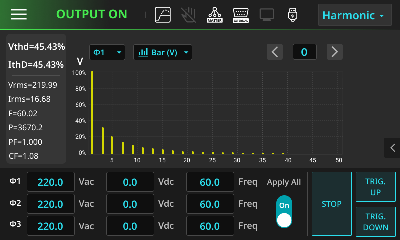
Built-in harmonic analysis and a real-time waveform monitor help engineers evaluate power quality and output behavior. View voltage and current THD, harmonic distribution through the 50th order, and three-phase waveforms for validation and troubleshooting.

Harmonic Analysis
Measure voltage and current total harmonic distortion (THD) in real time, with detailed analysis from the fundamental through the 50th harmonic. Harmonic amplitude, percentage, and phase information are displayed alongside key electrical parameters, including voltage, current, frequency, active power, power factor, and crest factor.
Both Table and Bar Chart views are available, allowing engineers to quickly evaluate harmonic distribution, distortion levels, and overall power quality.
Real-Time Waveform Monitor
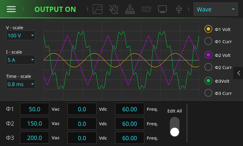
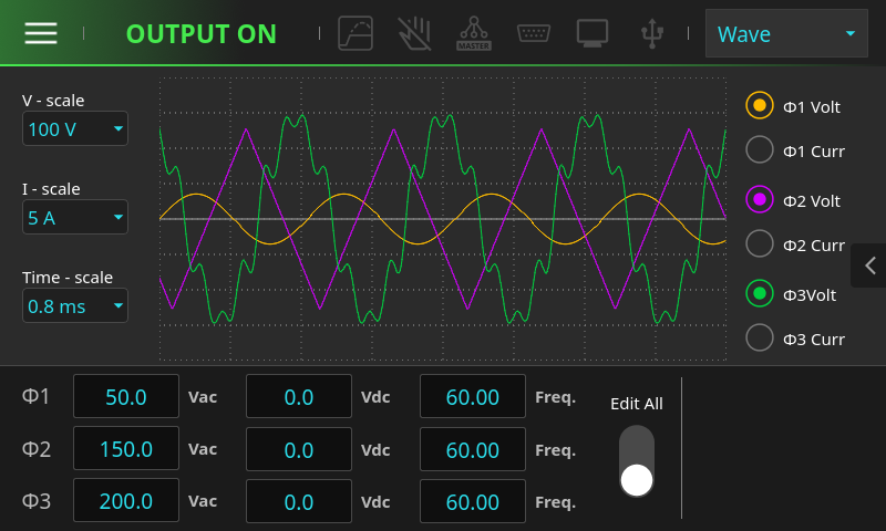
Monitor three-phase voltage and current waveforms simultaneously through an integrated oscilloscope-style interface. Individual phase channels, voltage and current scales, and the time base can all be adjusted for detailed waveform observation.
The intuitive graphical interface makes it easy to identify transient events, waveform anomalies, and output behavior, improving debugging efficiency and accelerating system validation.
Flexible Load Simulation for Real-World Power Validation
RPS-9000 load configurations provide regenerative AC and DC electronic loading for power conversion systems, energy storage, chargers, and other high-power equipment. Programmable load modes reproduce electrical characteristics for performance and transient-response testing. Available functions depend on the selected configuration.
AC Electronic Load
Support a wide range of programmable load modes to simulate both ideal and real-world AC load characteristics.
- CC Mode – Constant Current
- CR Mode – Constant Resistance
- CP / CS Mode – Constant Power and Constant Apparent Power
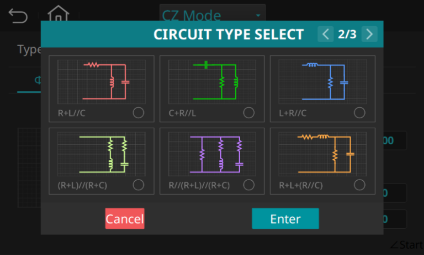
- CZ Mode – Programmable impedance with configurable R, L, and C parameters for realistic load simulation
In addition, lead and lag power factor settings, crest factor adjustment, and programmable impedance enable accurate simulation of inductive, capacitive, and non-linear loads encountered in practical applications.
DC Electronic Load
Integrated DC load functions support the most commonly used operating modes for power supply and battery testing.
- CC Mode – Constant Current
- CV Mode – Constant Voltage
- CP Mode – Constant Power
- CR Mode – Constant Resistance
- CCD / CRD Dynamic Modes – Dynamic current and resistance loading for transient response evaluation
These programmable load modes provide flexible testing for DC power supplies, battery systems, DC converters, and other power electronic devices.
Programmable Impedance Simulation (CZ Mode)
Simulate realistic AC load characteristics by configuring resistance (R), inductance (L), and capacitance (C) to reproduce the electrical behavior of real-world equipment. CZ Mode enables accurate impedance-based testing for motors, transformers, power converters, EV chargers, UPS systems, and other AC-powered devices, providing a more realistic validation environment than conventional constant-current or constant-power load modes.
One Platform. Multiple Power Configurations.
From 202.5 kVA / kW to Megawatt-Scale Testing
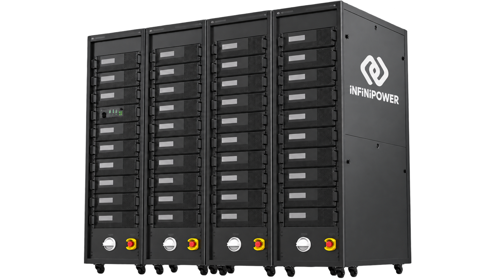
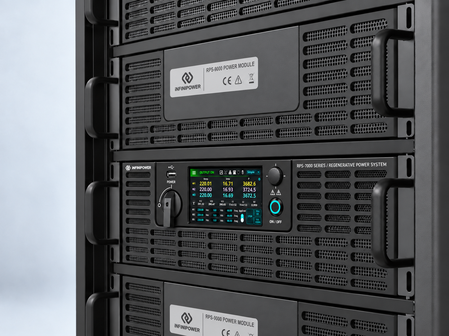
Start with the single-cabinet RPS-9200 and select configurations up to the four-cabinet RPS-9800. Multiple systems can operate in parallel up to 8 MW to meet growing requirements in AI infrastructure, charging, energy storage, and renewable energy validation.
Advanced Power Simulation & Measurement
LIST / STEP / PULSE / TRANSIENT
Build programmable transient sequences with controlled voltage, frequency and timing changes.
Waveform Library
Select Sine, Square, Triangle, Clipped Sine and user-defined waveforms.
DST Waveforms
Apply built-in distorted waveforms and harmonic synthesis for power-quality simulation.
Real-Time Waveform Monitor
View voltage and current waveforms in real time during operation.
Detail Measurement Mode
Review up to 15 key electrical parameters together on one screen.
IEC 61000-4-11 Testing
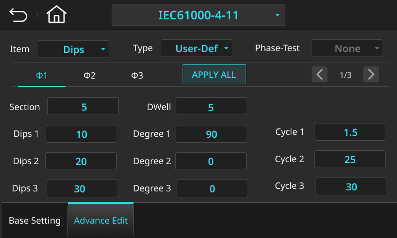
Configure voltage dip and interruption tests for repeatable compliance validation.
AIOT Intelligent Predictive Maintenance
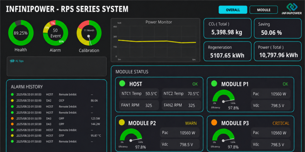
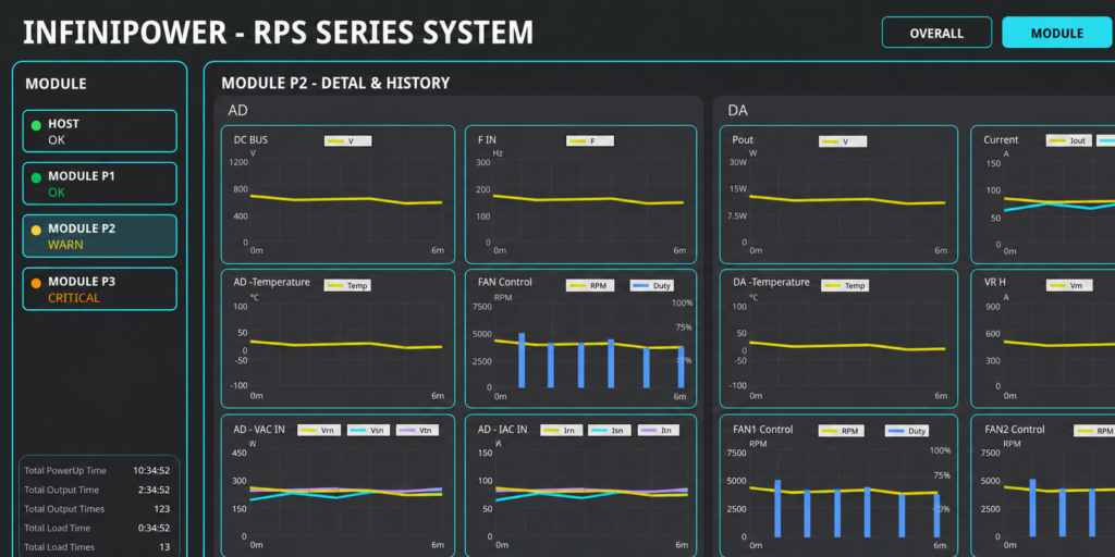
PowerSense™ combines real-time system monitoring, intelligent diagnostics, historical analysis, and predictive maintenance for the RPS series. Track equipment health, alarms, efficiency, and recovered energy to identify abnormal trends and support planned service.
Real-Time System Visibility
Monitor output, efficiency, regenerated energy, system status and event activity in one clear operational view.
Intelligent Diagnostics & Predictive Service
Track equipment health and operating trends to identify potential issues early and support planned maintenance.
Selection Guide
| Model | AC Power (kVA) DC Power (kW) | AC Current 1-phase (Arms) | AC Current 3-phase (Arms/phase) | 42U Cabinets |
|---|---|---|---|---|
| RPS-9200 | 202.5 | 1296 | 432 | 1 |
| RPS-9270 | 270 | 1728 | 576 | 2 |
| RPS-9330 | 337.5 | 2160 | 720 | 2 |
| RPS-9400 | 405 | 2592 | 864 | 2 |
| RPS-9470 | 472.5 | 3024 | 1008 | 3 |
| RPS-9540 | 540 | 3456 | 1152 | 3 |
| RPS-9600 | 607.5 | 3888 | 1296 | 3 |
| RPS-9670 | 675 | 4320 | 1440 | 4 |
| RPS-9740 | 742.5 | 4752 | 1584 | 4 |
| RPS-9800 | 810 | 5184 | 1728 | 4 |
Maximum RMS current is specified at 125 V working voltage. Split-phase rated power is two-thirds of the listed model rating. Output remains subject to model-specific voltage, current and power limits. See the datasheet for complete specifications and test conditions.
Common Specifications
| AC Input | 380–480 V L-L ±10%, 3-phase, 47–63 Hz |
|---|---|
| Standard AC Output | 0–350 V L-N / 0–606 V L-L (3-phase); 0–700 V L-L (split-phase) |
| Optional AC Output | 0–400 V L-N / 0–692 V L-L (3-phase); 0–800 V L-L (split-phase) |
| Standard DC Output | ±495 V; ±990 V in split-phase |
| Optional DC Output | ±565 V; ±1130 V in split-phase |
| Output Frequency | DC, 30–150 Hz; 30–1000 Hz optional |
| Voltage THD | <0.4% at 50/60 Hz; <0.8% at 30–150 Hz, under stated datasheet conditions |
| Harmonic Synthesis | Through the 50th order at 50/60 Hz fundamental |
| Interfaces | USB, Ethernet, GPIB and external I/O (DB25); CAN Bus optional |
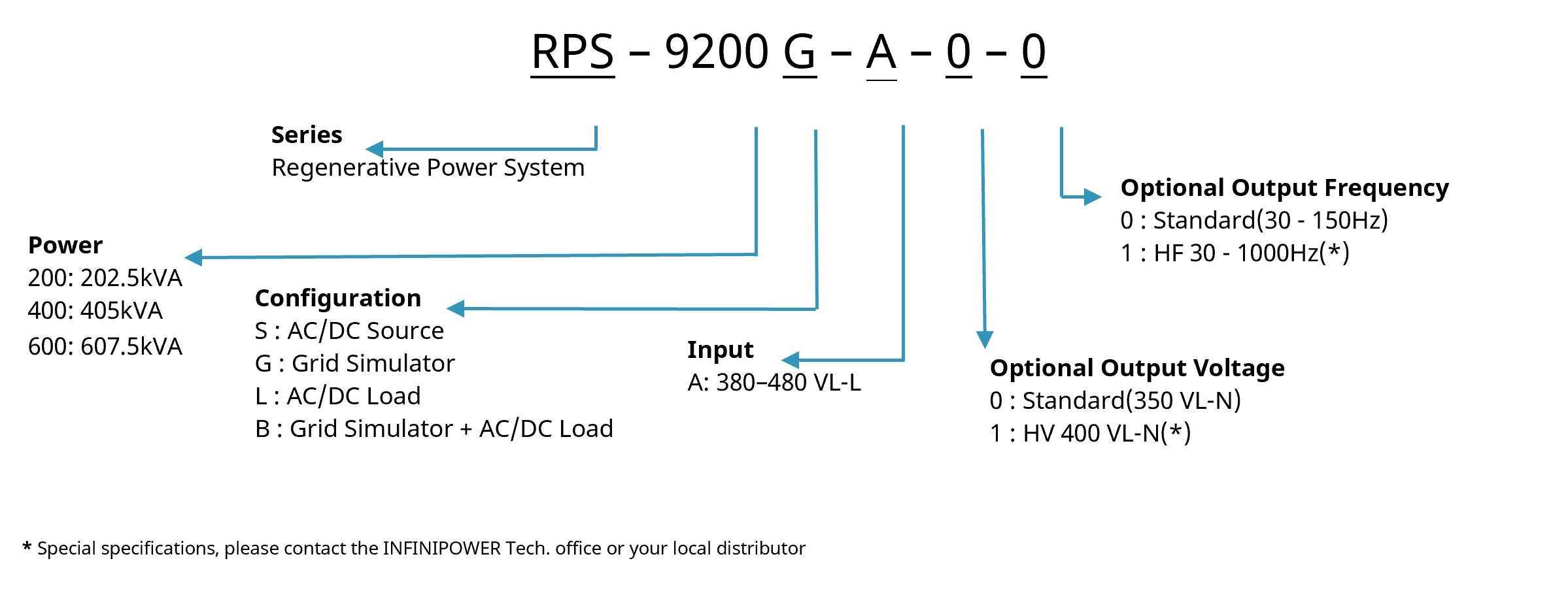
Ordering Information

Accessories List
| Typical Delivery Items | Optional Accessories |
|---|---|
| Regenerative Power System | Parallel cable (DisplayPort) |
| USB cable (Type A to Type B), 5 m | CAN Bus interface card / CAN Bus cable, 5 m |
| LAN cable CAT5E, 5 m | GPIB cable, 5 m |
| DB25 adapter board (for I/O signals) | DB25 male-to-male adapter |
| Test report | Output voltage calibration fixture (remote sense cable) |
| — | RPS-9000 series input power cable, 5 m |
For special specifications, please contact INFINIPOWER or your local distributor.
Together, we make a difference.
In the testing of new energy equipment, stability and reliability are crucial. InfiniPower relies on the design verification of the world's leading brands and the quality assurance of world-class smart manufacturing plants to provide you with test power solutions that can stand the test of time. Join us to help you meet stringent product performance and compliance requirements with the highest quality power support, and drive a sustainable production future!