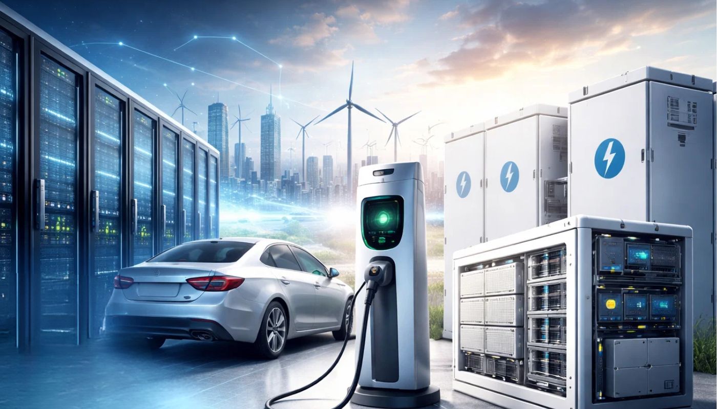
As the world transitions to new energy sources, power systems play an increasingly central role in the energy transformation process. Whether it’s electric vehicles, renewable energy generation, or energy storage systems, these technologies depend on stable and reliable power management. To ensure optimal performance under various operating conditions, electronic load devices are essential tools in testing phases.
Electronic load equipment can precisely simulate a variety of load conditions, such as Constant Current (CC) or Constant Voltage (CV), helping engineers test and optimize the design of power systems in laboratory environments. This ensures that these systems can handle complex workloads and adapt to the various fluctuations common in real-world applications.
Core Functions of Electronic Loads:
- Performance Optimization: By simulating diverse real-world load scenarios, engineers can identify and address potential issues during the design phase, improving system stability and performance.
- Reliability Testing: Electronic loads can replicate long-term operating conditions, helping verify a power system’s reliability and longevity, particularly under high-power, high-temperature, or other extreme conditions.
- Protection Mechanism Verification: Electronic loads are used to test protection features (e.g., overload, short-circuit protection) to ensure safe operation in harsh conditions.
Given these capabilities, electronic load equipment is indispensable. It not only supports thorough performance validation during product development and testing but also simulates complex conditions to ensure that power systems remain stable and reliable across different environments.
Below, we explore the core roles of electronic loads in performance optimization, reliability testing, and protection mechanism verification in greater detail.
1. Types and Functions of Electronic Load Equipment
1.1 DC Electronic Loads
Definition and Function:
DC electronic loads test DC power sources by precisely controlling current or voltage to emulate various load conditions. They are commonly used to evaluate batteries, chargers, DC-DC converters, and other DC devices.
Typical Application Scenarios:
- Battery Discharge Testing:
DC loads can simulate different discharge conditions to assess battery capacity, internal resistance, discharge efficiency, and safety. Using CC mode, engineers can replicate real-world load profiles, critical in electric vehicles, energy storage, and renewable energy systems. - Photovoltaic (PV) Module Testing:
In PV systems, DC loads can emulate module operating conditions by adjusting load parameters to evaluate efficiency under varying illumination and power outputs, providing insights into real-world PV performance.
Operating Modes:
- Constant Current (CC): Keeps a stable current output, ideal for battery discharge tests.
- Constant Voltage (CV): Maintains a stable voltage to test a power supply’s voltage regulation capability.
- Constant Power (CP): Simulates a constant-power load, suitable for testing dynamic response in PV modules and other devices.
- Constant Resistance (CR): Emulates a fixed resistance value, useful for evaluating internal resistance and line impedance.
1.2 AC Electronic Loads
Definition and Function:
AC electronic loads test AC power equipment by precisely simulating resistive, inductive, and capacitive loads. They are widely used for testing Uninterruptible Power Supplies (UPS), inverters, and AC motor drives.
Typical Application Scenarios:
- Inverter Testing:
Inverters are critical in new energy systems. AC loads can simulate complex AC load conditions, evaluating inverter performance under varying frequencies, power factors, and voltage fluctuations. For example, by mimicking different power factor loads, engineers can assess how well inverters handle complex, real-world load scenarios. - UPS System Testing:
In UPS testing, AC loads simulate conditions like grid outages and voltage fluctuations. This verifies the UPS’s output stability and efficiency under emergency or transient conditions.
Differences from DC Electronic Loads:
- Operating Principles: DC loads focus on DC sources (batteries, PV modules), while AC loads target AC equipment (UPS, inverters).
- Application Fields: DC loads for DC power system testing; AC loads for AC systems and inverter testing.
- Load Characteristics: AC loads can simulate more complex load profiles, including resistive, inductive, and capacitive elements essential in AC testing.
1.3 Regenerative Electronic Loads
Definition and Function:
Regenerative electronic loads can return absorbed energy back to the grid or storage system, reducing test energy consumption. They emulate various load conditions while minimizing energy waste, suitable for long-duration high-power testing.
Typical Application Scenarios:
- New Energy Charging Equipment Testing:
For EV charging stations or other high-power chargers, regenerative loads efficiently test dynamic responses and efficiency under large currents. Energy recovery reduces consumption and heat loss during long, high-power tests. - Long-Duration High-Power Equipment Testing:
Ideal for continuous high-power applications like inverter, PV, or wind power endurance tests. Regenerative loads lower overall energy consumption, improving both cost-effectiveness and environmental friendliness.
By understanding DC, AC, and regenerative electronic loads, readers can appreciate their importance and broad applications in new energy technology testing.
2. Operating Modes of Different Electronic Loads and Their Applications
2.1 Constant Current (CC) Mode
Definition and Principle:
In CC mode, the electronic load adjusts internal impedance to maintain a constant current, regardless of input voltage changes. This mode is ideal for evaluating a power source’s characteristics under steady current conditions.
Typical Applications:
- Battery Discharge Testing:
CC mode simulates real discharge scenarios, determining battery capacity, internal resistance, discharge efficiency, and lifecycle — critical for EV, grid storage, and renewable applications. - Power Adapter Stability Testing:
By applying different current loads, CC mode verifies the adapter’s ability to maintain stable output under heavy loads.
2.2 Constant Voltage (CV) Mode
Definition and Principle:
CV mode maintains a stable input voltage by adjusting impedance. Changes in output current do not affect the load’s target voltage.
Typical Applications:
- Charger Voltage Regulation Testing:
CV mode helps assess how well a charger stabilizes its output voltage under varying load conditions, especially at high or low loads. - DC Power Supply Stability Testing:
Simulating different load variations ensures the DC supply can maintain stable voltage output under different scenarios.
2.3 Constant Power (CP) Mode
Definition and Principle:
CP mode regulates the product of voltage and current to maintain a constant power value. It evaluates how the power source responds to varying power demands.
Typical Applications:
- DC-DC Converter Efficiency Testing:
DC-DC converters rely on stable efficiency across different power conditions. CP mode simulates various power loads to confirm consistent performance. - Inverter Power Testing:
CP mode can emulate constant-power consumption scenarios (e.g., household loads), assessing the inverter’s performance and stability under real-world power conditions.
2.4 Constant Resistance (CR) Mode
Definition and Principle:
CR mode maintains a constant internal resistance. As input voltage changes, the load automatically adjusts the current, useful for evaluating circuit impedance and internal resistance characteristics of power sources.
Typical Applications:
- Circuit Impedance Matching Tests:
In complex circuits, impedance matching is key to efficiency and signal quality. CR mode simulates fixed resistances to assess power supply impedance matching. - Battery Internal Resistance Evaluation:
Battery internal resistance affects charging/discharging efficiency and lifespan. CR mode accurately simulates various impedance conditions for in-depth battery analysis.
3. Selection Guide for Electronic Loads in New Energy Applications
3.1 Choosing an Electronic Load for Battery Testing
Battery Characteristics:
Different battery chemistries (e.g., Li-ion, lead-acid) behave differently during charge/discharge. Li-ion batteries are common in EVs and storage systems, while lead-acid batteries often appear in UPS systems.
Key Selection Criteria:
- Dynamic Response:
For fast-charge/discharge applications (like EV batteries), loads must have a high dynamic response to handle large, rapid current changes. - Energy Recovery for Long-Term Durability Tests:
For extended high-power tests, regenerative electronic loads feed energy back to the grid, reducing energy consumption and heat loss—ideal for large-scale, long-duration battery testing in new energy storage solutions.
3.2 Load Selection for Inverters and UPS Systems
Complex Conditions for Inverters and UPS:
Inverters and UPSs face grid frequency fluctuations and transient conditions. High dynamic response AC loads help simulate these conditions, ensuring accurate performance evaluations.
Key Selection Criteria:
- AC Load Dynamic Response Speed:
The faster the response, the more accurately the load simulates real-world grid variations. - Energy Recovery for Prolonged UPS Stability Tests:
In long-term UPS tests, regenerative loads reduce energy consumption, especially at high outputs, improving overall test efficiency.
3.3 Electronic Load Selection for EV Chargers and Charging Stations
High-Power Requirements for Charging Equipment:
EV charging stations often handle large currents and power levels. Loads must remain stable under high-power, rapid-charge conditions.
Key Selection Criteria:
- Efficiency of Regenerative Loads:
For high-power charging gear, regenerative loads simulate charger demands while recovering energy, minimizing heat and energy loss. - Quick Mode Switching:
Since load conditions change rapidly during actual charging, electronic loads must quickly switch between CC, CV, and other modes to simulate various charging phases.
By analyzing these modes and using selection guidelines for batteries, inverters, UPSs, and charging stations, engineers can more accurately choose loads that meet their test requirements and ensure efficient, precise testing.
4. Five Key Factors for Choosing the Right Electronic Load
4.1 Power Range, Voltage, and Current Capability
Determining the Power Range:
Power range selection is critical. In new energy applications, large power demands are common. The electronic load’s power rating should exceed the device’s rated power by 10–20% to prevent overloads.
Voltage and Current Capability:
Consider maximum discharge currents and peak voltages, especially for battery and high-power charger tests. The load must match the output conditions of EV chargers or high-voltage DC sources.
4.2 Dynamic Response and Accuracy
Evaluating Response Speed:
Rapid response is crucial, especially in high-frequency power systems and fluctuating loads. For switch-mode power supplies, response rates above 1 kHz may be necessary to capture transient voltage/current fluctuations.
Importance of Accuracy:
Accuracy ensures reliable data. High-precision loads (±0.1% or better) provide trustworthy test results, vital for validating power supply performance or verifying design parameters.
4.3 Support for Multiple Operating Modes and Fast Switching
Impact of Switching Speed on Test Results:
Multi-mode support and fast switching enhance test flexibility. For complex scenarios (e.g., inverter or charger tests), quick transitions between CC and CP modes ensure continuous, stable testing.
This capability is especially important for inverter tests, where sudden load changes simulate real-world grid conditions, assessing transient response and system resilience.
4.4 Automation and Programmability
Trend Towards Automated Testing:
As test scenarios grow more complex, automation is increasingly vital. Modern electronic loads often feature programmable interfaces (USB, GPIB, RS232) and automation controls. Automated testing saves time, reduces human error, and accelerates data analysis.
In repetitive or batch tests, automation dramatically improves efficiency and ensures consistent, accurate results.
4.5 Protection Features and Safety
Ensuring Safety:
At high power and current, risks increase. Comprehensive protection functions—Over-Voltage Protection (OVP), Over-Current Protection (OCP), Over-Temperature Protection (OTP), and short-circuit protection—prevent damage to both the load and the DUT.
- OVP: Disconnects circuit if input voltage exceeds rating.
- OCP: Reduces current or enters protection mode if max current is exceeded.
- OTP: Lowers power or shuts down if temperature is too high.
Multiple protection features increase test safety and prolong equipment lifespan.
5. Selection Strategies for Different Application Scenarios
Case 1: Battery Charge/Discharge Testing
For battery discharge tests, fast dynamic response is crucial. CC mode is primary for controlling discharge current. Energy recovery loads are ideal for long-term durability tests, reducing energy consumption in EV battery evaluation.
Case 2: Power Adapter Testing
Power adapters require testing across various load conditions, from light to full load. Loads supporting CC, CV, and CP modes with fast switching simulate real use cases. CC mode checks current stability, CV mode tests voltage regulation, and CP mode evaluates efficiency under dynamic conditions.
Case 3: Inverter and UPS Testing
In complex inverter and UPS scenarios, AC loads simulate transient grid fluctuations. Regenerative loads return consumed energy to the grid, lowering test costs and heat dissipation. This is essential for long-term, high-power endurance testing and improving system efficiency.
By considering power range, dynamic response, mode switching, automation, and protection, as well as adapting strategies to specific scenarios, engineers can select the optimal electronic load for their test needs.
6. Future Trends in Electronic Load Equipment
6.1 Higher Bandwidth and Dynamic Response
Importance of High Bandwidth:
As switching frequencies increase in power electronics—especially in EV charging and DC-DC converters—faster load response is essential. High bandwidth allows loads to capture transient fluctuations and deliver more accurate, stable test results.
Technical Advances:
Future loads will achieve higher frequencies (tens of kHz or more), meeting the demands of advanced BMS, smart grids, and ultra-fast charging, ensuring more precise and reliable testing.
6.2 Intelligent and Automated Testing Functions
AI and Automation Integration:
With AI and automation, future electronic loads will analyze test data in real-time, automatically optimizing test parameters. AI-driven loads predict load curves and adjust testing strategies, improving efficiency and reducing human error.
Integrated Automated Platforms:
Future systems will integrate seamlessly with test management software and data analysis tools, creating end-to-end automated testing solutions. This leads to faster, more comprehensive testing workflows and improved accuracy.
6.3 Higher Power Density and Energy Recovery
Energy Recovery Technology:
As sustainability gains importance, energy recovery in electronic loads will become mainstream. Regenerative loads feed energy back to the grid or storage, enabling “green testing” that conserves energy and reduces heat dissipation.
Power Density Improvements:
Through better thermal management (e.g., liquid cooling) and optimized circuit design, future loads will achieve higher power density, handling large power outputs in smaller footprints—vital for testing PV inverters, wind systems, and EV chargers efficiently.
Green Testing and Sustainability:
Loads with efficient energy recovery and intelligent management reduce energy waste and emissions, aligning with corporate sustainability goals and offering competitive advantages in the evolving renewable energy market.
With higher bandwidth, smarter automation, and improved energy recovery, future electronic loads will play an even more pivotal role in new energy testing, boosting efficiency, accuracy, and sustainability.
Conclusion: Choosing the Right Electronic Load for New Energy Applications
Selecting the right electronic load is critical to successful testing in new energy applications. These systems—encompassing batteries, EV chargers, inverters, and UPS—require electronic loads that can replicate real-world conditions accurately. By doing so, engineers can identify design flaws and optimize performance.
Key Takeaways:
- Power, Voltage, and Current Capability: Ensure the load’s power rating and electrical parameters exceed the DUT’s requirements.
- Dynamic Response and Accuracy: High bandwidth and precision are crucial for capturing fast transients and verifying stable operation.
- Multiple Operating Modes and Fast Switching: Flexible modes and quick transitions simulate various scenarios, essential for complex systems like inverters and EV chargers.
- Automation and Intelligent Functions: Programmability and automated testing reduce labor, accelerate processes, and improve data accuracy.
- Protection and Safety: Comprehensive protection ensures both test equipment and DUT safety, improving reliability and extending equipment life.
As new energy technologies evolve, electronic loads will become more intelligent, energy-efficient, and capable of handling rapid changes and complex conditions. These advancements help engineers meet the growing demands of the renewable energy industry.
Choose Infinipower’s high-precision electronic load equipment to meet all your new energy testing needs. Whether for batteries, inverters, chargers, or UPS systems, our loads provide accurate and efficient testing solutions. Enhance test accuracy, optimize device performance, and drive innovation in the new energy sector. Contact our technical team today to learn how our advanced electronic loads can elevate your power testing capabilities!