1. Introduction and Context
The rapid expansion of electric vehicle (EV) adoption has driven the development of international standards that govern EV charging. In North America, SAE J1772 is the de facto specification for AC conductive charging systems. Developed by SAE International, J1772 defines the electrical interface, connector geometry, communication protocols, and safety requirements between EVs and chargers.
Ensuring that EV chargers are rigorously tested against SAE J1772 is essential for user safety, system interoperability, and regulatory compliance. This article delves into the technical insights of SAE J1772, outlines critical test procedures, and provides a historical perspective on the standard’s evolution. For more on advanced EV testing solutions, visit our RPS-5000 Grid Simulator and Complete Guide for EV Testing pages.
2. Technical Overview of SAE J1772
2.1. Key Elements and Electrical Specifications
SAE J1772 outlines the essential specifications for EV conductive charging:
-
Electrical Interface:
- Supports AC charging up to 240 V.
- Current ratings range from 16 A (basic chargers) to higher values for advanced systems.
- Power output typically spans 3.3 kW to over 7 kW.
-
Connector Design:
- Standardized connector, also known as IEC 62196-2 Type 1 or J plug.
- Ensures physical compatibility between the vehicle inlet and charger.
-
Signal Protocol:
- Uses a 12 V control pilot (CP) and a proximity pilot (PP) to communicate charger readiness, available current, and cable integrity.
-
Protection Features:
- Incorporates isolation, overcurrent, and fault detection mechanisms to ensure safe operation.
2.2. Connector Design, Pilot Signals, and Protection Mechanisms
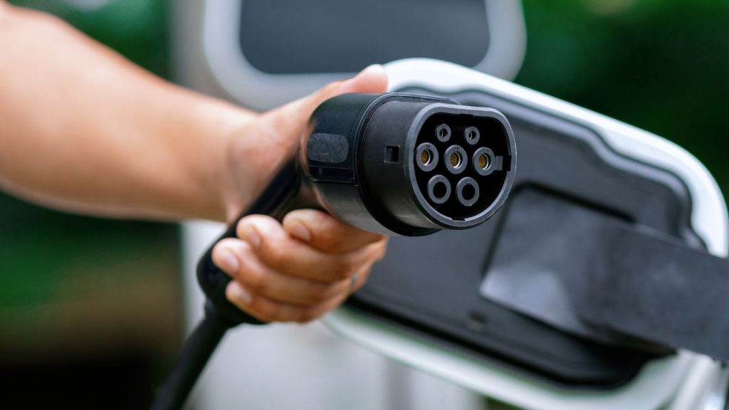
The SAE J1772 connector consists of five pins with defined roles:
- L1: AC line (live).
- N: Neutral.
- CP (Control Pilot): Communicates the charger’s operational state and maximum current capacity.
- PP (Proximity Pilot): Acts as a mechanical safety indicator to confirm a secure connection.
- PE (Protective Earth): Provides grounding for safety.
For instance, during charging, the CP pin delivers a modulated ±12 V, while the PP ensures that the connection is properly seated. Detailed communication and safety functions are vital for both residential and public charging applications. For further insights on EV communication, refer to our Automotive Ethernet Testing for EV page.
3. Importance of Charger Testing
3.1. Electrical Safety Testing
Charger testing verifies that EVSE complies with stringent safety criteria:
- Insulation Resistance Tests:
Confirm that live parts are safely isolated, typically requiring megohm-level resistance. - Overcurrent and Short-Circuit Tests:
Simulate fault conditions to ensure protective devices (e.g., circuit breakers, fuses) activate correctly. - Residual Current Device (RCD) Verification:
Check that leakage currents are detected and the circuit is disconnected promptly.
3.2. Communication and Pilot Signal Testing
Verifying the communication signals (CP and PP) is critical:
- Control Pilot (CP) Verification:
Test the modulation and voltage levels (commonly around 12 V) to accurately reflect charger readiness. - Proximity Pilot (PP) Testing:
Measure resistance values to confirm cable rating and a secure mechanical connection.
These tests ensure proper interaction between the EV and charger, enabling standardized plug-and-charge functionality.
3.3. Environmental and Mechanical Testing
Charger durability is validated under simulated real-world conditions:
- Thermal Testing:
Evaluates performance under extreme temperature variations. - Vibration and Shock Testing:
Ensures structural integrity and reliable operation during transportation and installation.
For a detailed workflow on EV testing, see our Complete Guide for EV Testing.
4. Detailed Overview and Historical Perspective of SAE J1772
This section draws from extensive historical and technical content (originally from Chinese language sources) to provide a deeper understanding of SAE J1772’s evolution and its connector details.
4.1. Historical Development and Industry Impact
SAE J1772 was originally introduced in the early 2000s under the impetus of the California Air Resources Board (CARB) to standardize EV charging. Early systems like the Avcon connector were used in vehicles such as the EV1, but limitations in power delivery and durability led to the development of a more robust standard.
- 2001: CARB set the J1772-2001 standard for EV charging in California.
- 2009: The revised J1772-2009 connector, developed by companies like Yazaki, was approved—supporting higher voltages and currents (up to 19.2 kW) compared to earlier designs.
- 2010-2012: The revised standard was modified to meet the increasing power demands, resulting in widespread adoption by major automakers including Ford, General Motors, Toyota, and Tesla.
- Global Influence: Although originally a North American standard, J1772’s communication protocol has been integrated into international standards such as IEC 62196-2 (Type 1), ensuring broad interoperability.
4.2. Detailed Connector Specifications and Signal States
The physical characteristics of the SAE J1772 connector (J plug) include:
- Dimensions:
- Length: 33.5 mm (1.32 inches)
- Diameter: 43.8 mm (1.72 inches)
- Pins:
- 5 pins in total (L1, N, CP, PP, PE)
- CCS Combo 1 further adds two DC terminals for fast charging.
Connector Signal States Table
The following table summarizes the key CP/PP signal states as defined in the SAE J1772 specification:
| State | Description | CP-PE Resistance | Measured CP-PE Voltage |
|---|---|---|---|
| State A | Standby | Open or ∞ Ω | +12 V |
| State B | Vehicle Detected | ~2740 Ω | +9 ± 1 V |
| State C | Ready to Charge | ~882 Ω (with additional ~1300 Ω in parallel) | +6 ± 1 V |
| State D | With Ventilation Required | ~246 Ω (with ~270 Ω) | +3 ± 1 V |
| State E | No Power (Circuit Open) | — | 0 V |
| State F | Error | — | −12 V |
Additionally, the control pilot signal uses pulse-width modulation (PWM) to indicate the maximum current available. For example:
- 16% PWM corresponds to 10 A,
- 25% to 16 A,
- 50% to 32 A,
- 90% indicates a fast charging option.
For more technical details on signal processing in EV chargers, please refer to our Automotive Ethernet Testing for EV page.
5. Comparing Different Testing Series and Methodologies
5.1. Differences in Testing Equipment Series
EV charger test systems vary significantly:
- Basic Series: Focus primarily on electrical safety tests such as insulation resistance and overcurrent protection.
- Advanced Series: Integrate high-frequency signal analysis and environmental simulation, suitable for next-generation chargers.
- Modular Integration: Some systems combine both electrical and communication testing in a single platform, streamlining the test process.
For an overview of advanced testing capabilities, visit our RPS-5000 Grid Simulator.
5.2. Integration with Automotive Ethernet Testing
Modern EV chargers are incorporating automotive Ethernet to enhance communication reliability. Testing these interfaces ensures robust data transfer and can work in tandem with SAE J1772 protocols. This integrated approach supports smart charging features and remote monitoring. Learn more on our Automotive Ethernet Testing for EV page.
6. Practical Implementation and Testing Workflow
A typical SAE J1772 testing workflow includes:
6.1. Pre-Testing Setup and Inspection
- Visual/Mechanical Inspection: Verify connector assembly and cable integrity.
- Initial Electrical Measurements: Confirm voltage, current, and power ratings per design specifications.
6.2. Electrical Safety Testing
- Insulation Resistance Test: Apply high DC voltage and measure resistance (in megohms).
- Overcurrent and Short-Circuit Simulation: Use programmable loads to validate current interruption.
- RCD Verification: Simulate leakage currents and ensure the RCD trips within required limits.
6.3. Communication and Pilot Signal Verification
- Control Pilot Simulation: Use signal generators to emulate EV inputs and measure CP signal voltage and modulation.
- Proximity Pilot Testing: Measure resistance values to ensure the cable rating is correctly indicated.
6.4. Environmental and Durability Assessments
- Thermal Cycling: Test performance in a thermal chamber from −40 °C to +85 °C.
- Vibration Testing: Simulate mechanical shocks using a vibration table.
6.5. Data Analysis and Certification
- Digital Data Logging: Record and analyze test data.
- Compliance Review: Compare results with SAE J1772 criteria for final certification.
For a detailed guide on test procedures, check our Complete Guide for EV Testing.
7. Advanced Technical Insights and Future Trends
7.1. Enhancing Communication Protocols
Recent enhancements in SAE J1772 include:
- Bidirectional Communication: Allows real‑time adjustments based on vehicle feedback.
- Power Line Communication (PLC): Future implementations may leverage PLC (e.g., IEEE 1901) for higher data transfer rates without extra wiring.
7.2. Integration of Diagnostic and Monitoring Tools
Modern chargers now incorporate:
- Self-Diagnostic Routines: Automated self-tests for insulation and communication health.
- Remote Monitoring: Connectivity via OCPP for real‑time performance alerts and maintenance scheduling.
7.3. Functional Safety and Cybersecurity Trends
As connectivity increases:
- Functional Safety: Systems are designed to be fail‑safe in the event of faults.
- Cybersecurity Measures: Enhanced encryption, secure boot, and regular software updates protect against cyber threats.
7.4. Global Standards Harmonization
Efforts to align SAE J1772 with international standards (e.g., IEC 61851, IEC 62196) promote:
- Enhanced Interoperability: Easier compliance across different regions.
- Streamlined Production: Manufacturers benefit from unified testing protocols and certification processes.
For additional insights on these trends, explore our Complete Guide for EV Testing.
8. Case Studies: Real-World Implementation of SAE J1772 Testing
8.1. Enhancing Home Charger Safety
A leading home charger manufacturer integrated advanced RCD and insulation tests based on SAE J1772. By simulating fault conditions and verifying pilot signals under various environmental stresses, the product’s safety margin improved significantly—exceeding regulatory standards for residential use.
8.2. Public Charging Station Validation
A comprehensive test campaign for a public EV charging network included:
- Insulation and Hipot Tests: Verifying continuous operation safety.
- Communication Protocol Testing: Ensuring real‑time responsiveness with simulated EV inputs.
- Vibration and Thermal Cycle Testing: Assessing durability in outdoor, high‑usage environments.
The successful validation reduced field failures and reinforced the network’s reliability.
8.3. Best Practices
Key recommendations include:
- Comprehensive Pre-Deployment Testing: Incorporate both electrical and communication tests.
- Advanced Simulation Tools: Use state‑of‑the‑art equipment to emulate diverse EV models.
- Regular Maintenance and Re‑Testing: Establish periodic testing schedules, especially for public installations.
- Detailed Documentation: Maintain complete records for quality assurance and audits.
For further details, visit our Automotive Ethernet Testing for EV page.
9. Conclusion
Understanding and implementing SAE J1772’s technical specifications is crucial for developing safe, reliable, and efficient EV chargers. By following rigorous testing protocols—from electrical safety and communication verification to environmental durability—manufacturers can ensure compliance and deliver exceptional charging performance.
In an industry where safety, interoperability, and reliability are paramount, thorough SAE J1772 testing remains a cornerstone of EV charger design and deployment. As communication protocols, diagnostic tools, and global standards evolve, the future of EVSE testing promises even greater efficiency and performance.
Leverage advanced testing methodologies and Infinipower’s innovative platforms—such as our RPS-5000 Grid Simulator—to remain competitive in the EV market. For additional technical support, explore our Complete Guide for EV Testing and Automotive Ethernet Testing for EV pages.
References
- Harper, J. D. (2011). SAE Technical Paper Series: Advances in J1772 Charger Technology. SAE International. Retrieved from https://www.sae.org/publications/technical-papers
- Intertek. (2020, October 2). EVSE Testing and Global Certifications. Intertek. Retrieved from https://www.intertek.com/blog/2020/10-02-evse/
- SAE International. (n.d.). SAE J1772 – Standard for Electric Vehicle Conductive Charging Systems. Retrieved from https://www.sae.org/standards/content/j1772_201701/
- Tektronix. (n.d.). EV Charging Standards and Testing Solutions. Retrieved from https://www.tek.com/en/solutions/industry/automotive-test-solutions/evse-testing/ev-charging-standards
- Wikipedia. (2023). SAE J1772. In Wikipedia. Retrieved from https://en.wikipedia.org/wiki/SAE_J1772
- Additional references from the provided content (translated and adapted):
- CARB. (2001). SAE J1772-2001 Standard.
- Yazaki et al. (2009). SAE J1772-2009 Connector Specifications.
- IEEE. (2012). Proposed PLC and IEEE 1901 Integration for EV Charging.