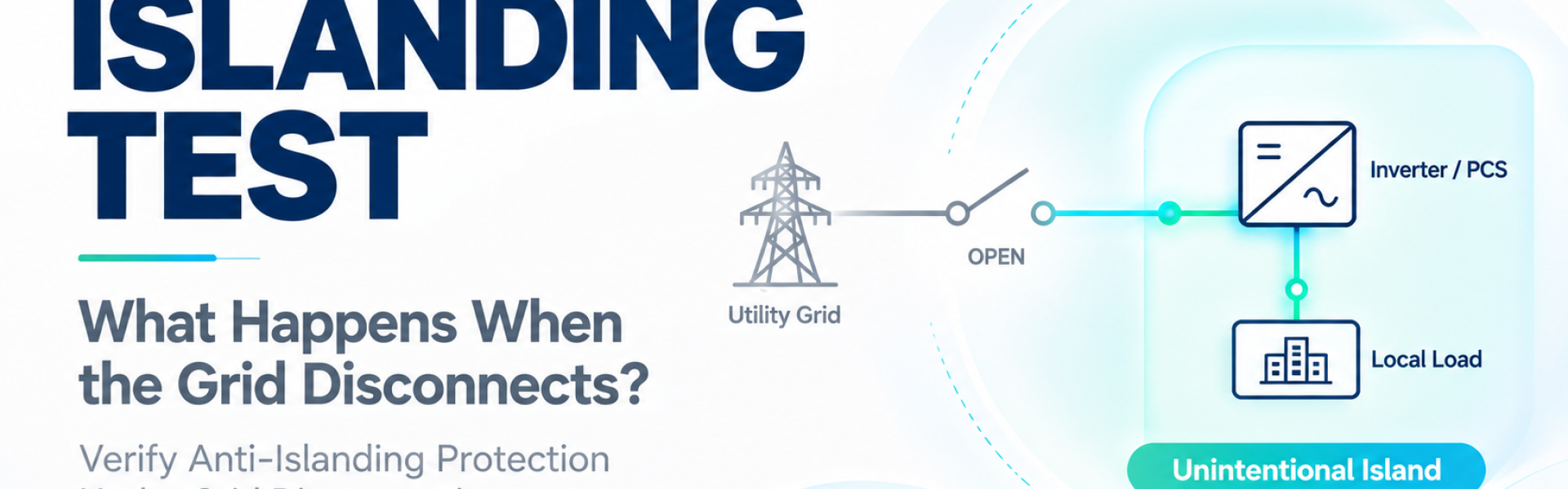
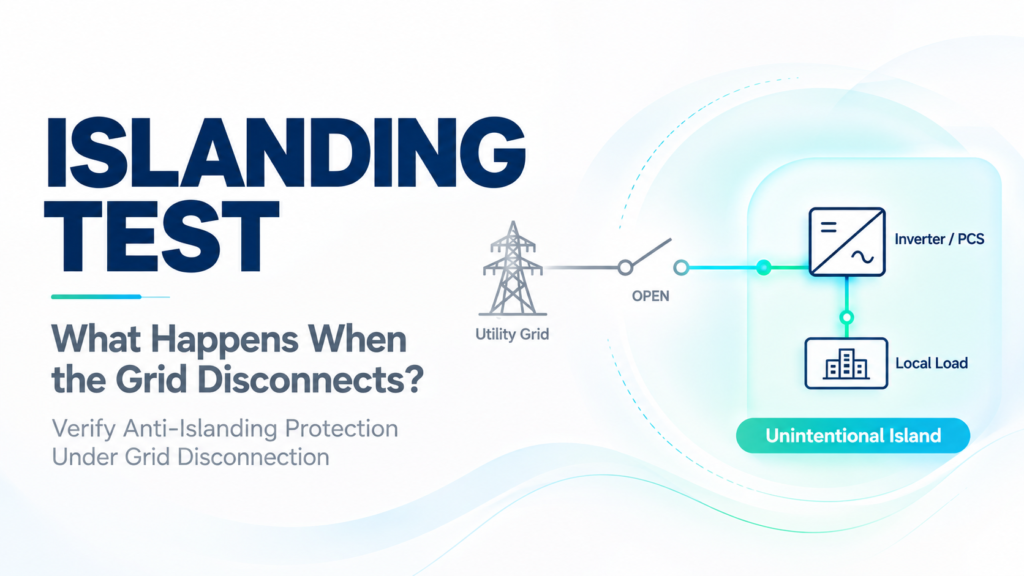
As solar power, energy storage systems, and bidirectional power conversion equipment become more widespread, power flow is evolving from one-way supply toward bidirectional architectures involving multiple energy resources. When the utility grid is suddenly interrupted, the ability of connected equipment to detect the abnormal condition and stop energizing an unintended island becomes an important issue for grid interconnection safety.
Islanding tests are essential for verifying this protection capability. This article explains how islands form, the principles of anti-islanding testing, the role of RLC loads, and how clear parameter settings and status monitoring help establish more consistent test procedures.
What Is Islanding and Why Can Lines Remain Energized After Grid Disconnection?
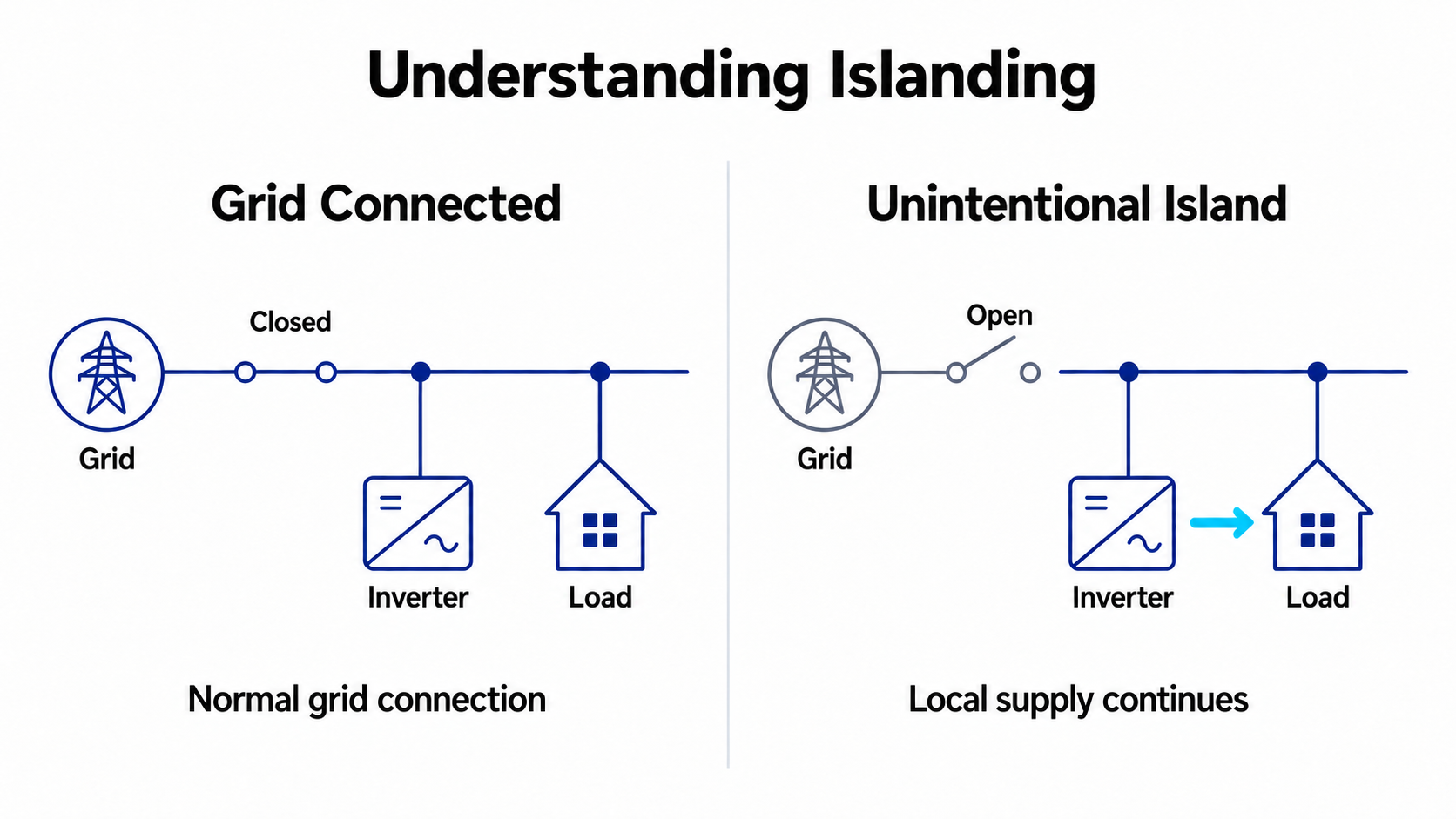
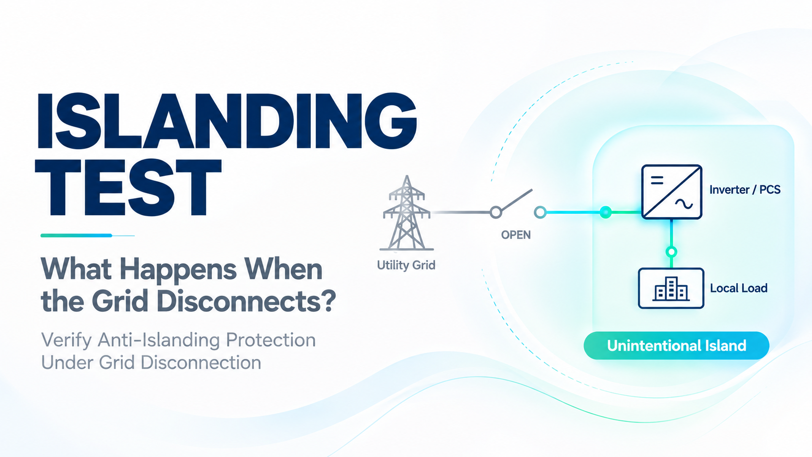
Islanding occurs when part of a power system separates from the utility grid while local generation continues supplying local loads, creating an independently operating electrical area.
For example, a solar inverter may operate in parallel with the utility grid and supply nearby loads. If an upstream switch opens and the inverter does not promptly detect the loss of the grid connection, it may continue supplying power, leaving lines energized even though they are expected to have lost their source.
Unintentional islanding can leave lines energized, allow voltage and frequency to operate without utility-grid regulation, and create risks from out-of-synchronism reclosing when the grid returns. Anti-islanding protection is intended to detect these conditions and stop continued energization of the island in accordance with applicable requirements.
Microgrids and energy storage systems may also intentionally enter off-grid operation using planned isolation and control mechanisms. Such intentional islands have different control objectives and verification requirements from the unintentional islands that anti-islanding protection is designed to prevent.
Why Is a Simple Power Interruption Test Insufficient to Verify Anti-Islanding Capability?
It may seem intuitive that voltage or frequency at the equipment terminals will change significantly as soon as the grid is lost. However, when local generation closely matches load demand, electrical parameters may temporarily remain within protection thresholds after disconnection, making the island more difficult to detect.
This presents a key challenge for anti-islanding verification: closely balanced generation and load can place greater demands on detection capability.
Testing therefore needs to do more than check whether equipment shuts down following an obvious loss of voltage. Specified generation and load conditions must be established before disconnecting the grid and observing the actual response. IEC 62116 provides test procedures for islanding prevention measures in utility-interconnected PV inverters to improve consistency and repeatability.
RLC Loads for Creating Challenging Islanding Conditions
Anti-islanding tests commonly use a parallel load consisting of resistance (R), inductance (L), and capacitance (C) to establish specified active power, reactive power, and resonance conditions.
| Component | Main Role in Testing |
|---|---|
| Resistance R | Consumes active power and adjusts power matching between the load and UUT output |
| Inductance L | Provides inductive reactive power and helps establish load resonance conditions |
| Capacitance C | Provides capacitive reactive power and works with inductance to adjust the resonant frequency |
Tuning the RLC load close to the fundamental grid frequency and closely matching the load to the equipment output creates an islanding scenario that can be more difficult to detect.
The quality factor (Qf) describes the resonant characteristics of the load. It differs from the power factor (PF) commonly shown on equipment interfaces and cannot be used interchangeably with it. Testing should verify R, L, C, quality factor, and power-matching conditions according to the applicable procedure, rather than checking total load power alone. Reference: IEC 62116 technical content
How Is an Islanding Test Performed? Connections Before and After Grid Disconnection
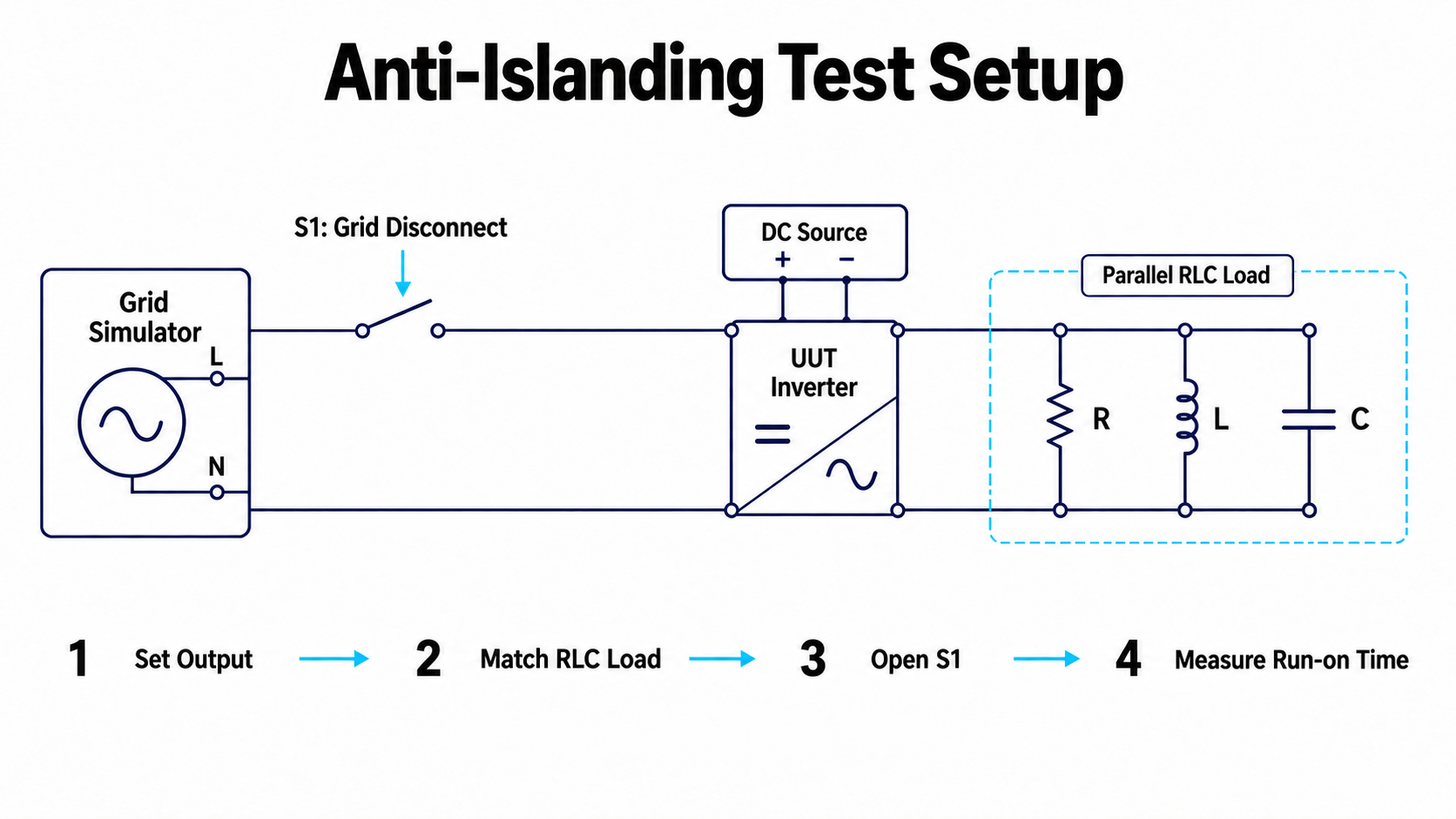
A typical test setup includes the grid or a grid simulator, the unit under test (UUT), an RLC load, and a switch for disconnecting the grid.
The key requirement is that the UUT and RLC load remain connected after the grid connection opens, so that the islanding condition to be evaluated can form.
The overall verification process can be divided into the following stages:
1. Establish grid-connected conditions
Set the voltage and frequency and bring the UUT to the specified output operating point.
2. Adjust load conditions
Configure the RLC load according to the test requirements and verify the actual active and reactive power.
3. Disconnect the grid
Open the grid-side connection while retaining the local circuit formed by the UUT and load.
4. Record the equipment response
Observe switch operation, voltage, and output current synchronously, and measure how long the equipment continues supplying power after the island forms.
5. Change conditions and repeat verification
Perform tests at different output power levels and load-matching conditions according to the applicable procedure.
When measuring run-on time, the start and end points must follow the definitions in the applicable specification. An alarm or status change on the equipment display alone is not sufficient as the basis for assessment.
Consistent Parameters and Measurements Support Reliable Test Results
Islanding test results depend on the UUT protection algorithm as well as the test platform settings and measurement methods.
In practice, particular attention should be paid to the following:
• Actual load values: Component tolerances and temperature rise may change the originally configured load conditions.
• Power matching: Measure actual power rather than relying only on rated values.
• Synchronization of switching and measurement: Record the actual grid-disconnection instant clearly to calculate response time correctly.
• Equipment operating settings: Record protection thresholds, control modes, and firmware versions.
Development verification and formal conformity testing also differ in scope. Successful cessation of power delivery under one set of conditions is not sufficient on its own; the test combinations required by the applicable standard must still be completed to assess conformity.
INFINIPOWER RPS Series for Clearer Test Settings and Circuit Status
During islanding tests, engineers need to track grid conditions, load parameters, switch status, and UUT responses simultaneously. When this information is spread across different screens, configuration and interpretation become more complex.
In the RPS islanding test interface provided for this article, three-phase voltage, frequency, RLC parameters, and S1/S2 switch status can be displayed together. Circuit diagrams and color coding indicate connections and energy flow in different modes, helping users understand the current test state.
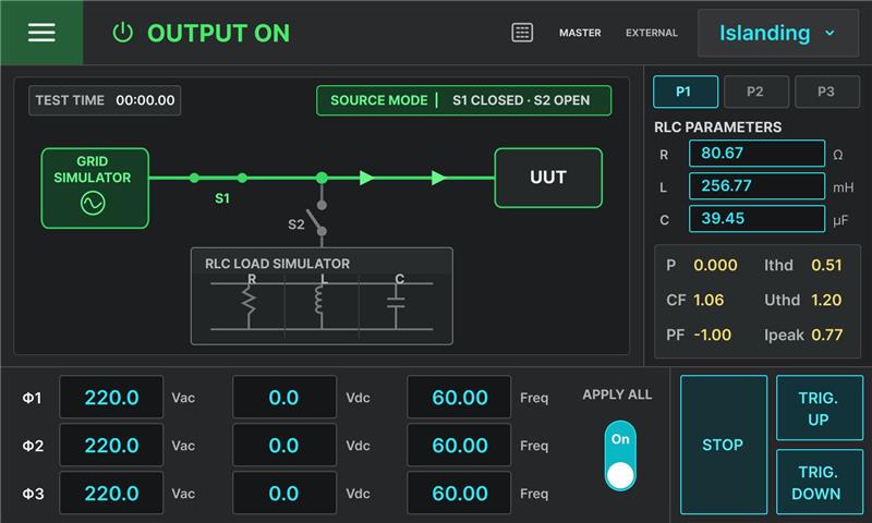
Figure: The RPS islanding test interface brings voltage, frequency, RLC parameters, and switch status together to help engineers understand the test configuration. Actual wiring and operating sequences depend on the system configuration and test procedure.
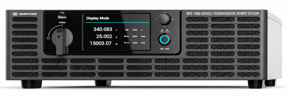
For test platforms that need to handle bidirectional energy flow from grid-connected equipment, the four-quadrant regenerative architecture of the INFINIPOWER RPS-7000 can serve as a basis for planning a grid simulation solution. A complete islanding test system must still be designed around UUT capacity, load requirements, the disconnect switch, and measurement configuration.
From Grid Disconnection Simulation to Reliable Protection Verification
Islanding tests evaluate whether equipment can correctly identify its operating condition after losing the utility grid and perform the intended protection action.
Every stage, from load matching and grid disconnection to waveform measurement, affects the reliability of the results. Clear, controlled, and repeatable test conditions help development teams identify protection blind spots more effectively and provide evidence for safety verification before grid interconnection.
Planning islanding tests for solar inverters or energy storage PCS? Contact the INFINIPOWER team to discuss suitable grid simulation and source/load configurations.